


 Home
-
Newly shipped PCBs
-
CLTE-XT 2-Layer 5.1mil PCB Ultra-Thin CLTE series laminate for ADAS and Patch Antennas
Home
-
Newly shipped PCBs
-
CLTE-XT 2-Layer 5.1mil PCB Ultra-Thin CLTE series laminate for ADAS and Patch Antennas
CLTE-XT 2-Layer 5.1mil PCB Ultra-Thin CLTE series laminate for ADAS and Patch Antennas
Printed Circuit Boards are custom-made products; the images and specifications provided are for reference only.
1. Rogers CLTE-XT PCB Introduction
CLTE-XT high frequency PCB is a high-performance laminate composed of micro-dispersed ceramic filler, PTFE, and woven fiberglass reinforcement, engineered to deliver improved loss tangent and the lowest insertion loss in its category. Building on the proven reliability of Rogers CLTE series, CLTE-XT PCB material maintains consistent electrical and mechanical properties across an extended temperature range, providing exceptional dimensional stability for demanding high-frequency applications.
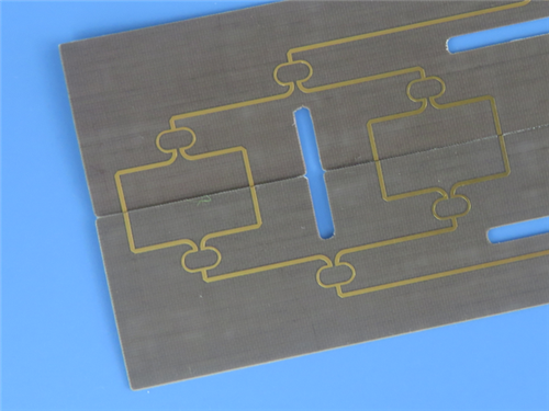
2. PCB Construction Details
Specification Category |
Details |
Base Material |
Rogers CLTE-XT |
Layer Count |
2 Layers |
Board Dimensions |
63mm x 35mm (±0.15mm) |
Finished Thickness |
0.25mm |
Copper Weight |
1 oz Outer Layers |
Min. Trace/Space |
5/6 mils |
Min. Hole Size |
0.3mm |
Blind Vias |
None |
Surface Finish |
Immersion Gold |
Solder Mask/Silkscreen |
None |
Electrical Test |
100% |
3. Stackup Structure
CLTE-XT 2-layer rigid PCB utilizes a single CLTE-XT core with a thickness of 0.129mm (5.1mil), sandwiched between two 35μm copper layers, creating a compact 0.25mm overall profile ideal for space-constrained applications.
4.Board Statistics
Components: 6
Total Pads: 27 (15 Thru-Hole, 12 Top SMT)
Vias: 8
Nets: 2
Files: Gerber RS-274-X
Standard: IPC-Class-2
Availability: Worldwide
5. CLTE-XT Material Features
Dielectric Constant: 2.79-2.94 @ 10GHz
Dissipation Factor: 0.0010
Thermal Coefficient of Dk: -8 ppm/°C
CTE: X 12.7/Y 13.7/Z 40.8 ppm/°C
Td: 539°C
Moisture Absorption: 0.02%
Tightest Dk Tolerance in CLTE Family (±0.03)
6. CLTE-XT Key Benefits
Enhanced plated through-hole reliability
Consistent lot-to-lot performance repeatability
Reduced circuit loss with maintained dimensional stability
Stable dielectric constant across temperature variations
Reduced stress when attached to ceramic active devices
7. Typical Applications
Advanced Driver Assistance Systems (ADAS)
Patch Antennas and Phased Array Antennas
Power Amplifiers
Ground-based and Airborne Communication Systems
Radar Systems
8.Data Sheet (CLTE-XT laminates)
Properties |
CLTE-XT PCB |
Units |
Test Conditions |
Test Method |
|
Electrical Properties |
|||||
Dielectric Constant |
2.94 |
- |
23˚C @ 50% RH |
10 GHz |
IPC TM-650 2.5.5.5 |
Dissipation Factor |
0.0010 |
- |
23˚C @ 50% RH |
10 GHz |
IPC TM-650 2.5.5.5 |
Dielectric Constant (design) |
2.93 |
- |
C-24/23/50 |
10 GHz |
Microstrip Differential Phase Length |
Thermal Coefficient of Dielectric Constant |
-8 |
ppm/˚C |
-50°C to 150°C |
10 GHz |
IPC TM-650 2.5.5.5 |
Volume Resistivity |
4.25x10⁸ |
Mohm-cm |
C-96/35/90 |
- |
IPC TM-650 2.5.17.1 |
Surface Resistivity |
2.49x10⁸ |
Mohm |
C-96/35/90 |
- |
IPC TM-650 2.5.17.1 |
Electrical Strength (dielectric strength) |
1000 |
V/mil |
- |
- |
IPC TM-650 2.5.6.2 |
Dielectric Breakdown |
58 |
kV |
D-48/50 |
X/Y direc- tion |
IPC TM-650 2.5.6 |
PIM (For antenna only) |
- |
dBc |
- |
50 ohm |
43dBm 1900 MHz |
Thermal Properties |
|||||
Decomposition Temperature (Td) |
539 |
˚C |
2hrs @ 105˚C |
5% Weight Loss |
IPC TM-650 2.3.40 |
Coefficient of Thermal Expansion - x |
12.7 |
ppm/˚C |
- |
-55˚C to 288˚C |
IPC TM-650 2.4.41 |
Coefficient of Thermal Expansion - y |
13.7 |
ppm/˚C |
- |
-55˚C to 288˚C |
IPC TM-650 2.4.41 |
Coefficient of Thermal Expansion - z |
40.8 |
ppm/˚C |
- |
-55˚C to 288˚C |
IPC TM-650 2.4.41 |
Thermal Conductivity |
0.56 |
W/(m.K) |
- |
z direction |
ASTM D5470 |
Time to Delamination |
>60 |
minutes |
as-received |
288˚C |
IPC TM-650 2.4.24.1 |
Mechanical Properties |
|||||
Copper Peel Strength after Thermal Stress |
1.7 |
N/mm (lbs/ in) |
10s @288˚C |
35 μm foil |
IPC TM-650 2.4.8 |
Flexural Strength (MD, CMD) |
40.7, 40.0 |
MPa (ksi ) |
25˚C±3˚C |
- |
ASTM D790 |
Tensile Strength (MD, CMD) |
29.0, 25.5 |
MPa (ksi ) |
23C/50RH |
- |
ASTM D638 |
Flex Modulus (MD. CMD) |
3247, 3261 |
MPa (ksi ) |
25C±3C |
- |
ASTM D790 |
Dimensional Stability (MD, CMD) |
-0.37, -0.67 |
mm/m |
4 hr at 105˚C |
- |
IPC-TM-650 2.4.39a |
Physical Properties |
|||||
Flammability |
V-0 |
- |
- |
C48/23/50 & C168/70 |
UL 94 |
Moisture Absorption |
0.02 |
% |
E1/105+D24/23 |
- |
IPC TM-650 2.6.2.1 |
Density |
2.17 |
g/cm³ |
C-24/23/50 |
- |
ASTM D792 |
Specifc Heat Capacity |
0.61 |
J/g˚K |
2 hours at 105˚C |
- |
ASTM E2716 |
NASA Outgassing |
0.02 / 0.00 |
% |
|
TML/CVCM |
ASTM E595 |
9.Why Choose CLTE-XT RF PCB?
CLTE-XT RF PCB board delivers exceptional high-frequency performance in an ultra-thin 0.25mm profile, combining low insertion loss, stable dielectric properties, and reliable plated through-hole integrity for demanding applications in automotive, aerospace, and telecommunications.
10.Order Now for ADAS and Radar Solutions!
Incorporate this high-performance Rogers CLTE-XT PCB into your next RF design for superior signal integrity and reliability in critical applications. Contact us today to discuss your project requirements and receive competitive pricing.