


 Home
-
Hybrid PCB
-
Rogers 4003 4-Layer Hybrid PCB 8mil RO4003C and Dual 5mil Tg170 FR4 Prepreg PCB for Base Station and Automotive Radar Applications
Rogers 4003 4-Layer Hybrid PCB 8mil RO4003C and Dual 5mil Tg170 FR4 Prepreg PCB for Base Station and Automotive Radar Applications
Printed Circuit Boards are custom-made products; the images and specifications provided are for reference only.
1. Introduction
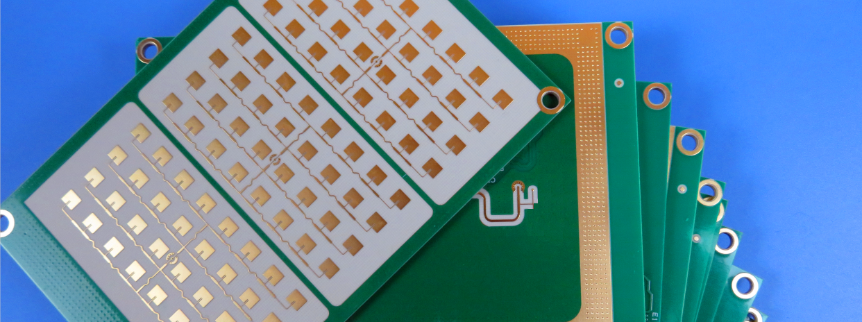
4-layer hybrid dielectric Rogers 4003 PCB is a rigid multilayer high-frequency printed circuit board built on 8mil Rogers RO4003C laminate paired with two pieces of 5mil Tg170 FR4 prepreg. This Rogers 4003 hybrid PCB adopts mixed dielectric stackup design, combining high-performance Rogers RO4003C RF substrate and high Tg FR4 bonding material. The 0.556mm total pressed thickness Rogers 4003 PCB balances low RF signal attenuation, mechanical reliability and manufacturing cost. This 4-layer Rogers 4003 PCB uses 0.5oz inner copper and 1oz finished outer copper, with green solder mask, white top silkscreen, no bottom silkscreen and immersion gold surface finish, ideal for cost-sensitive microwave and RF circuit designs.

2. Features
- Stable Dk of 3.38 +/-0.05 at 10 GHz, low dissipation factor of 0.0027 at 10GHz for the RO4003C core layer
- Tg170 FR4 prepreg delivers high thermal resistance, withstands multiple SMT reflow cycles without delamination
- Hybrid dielectric stackup precisely controls total laminated thickness at 0.556mm for tight thickness tolerance
- Copper matched CTE of RO4003C reduces thermal stress; special lamination profile controls board warpage risk
- 1oz outer finished copper, 0.5oz inner copper construction, green solder mask top with white silkscreen, immersion gold surface treatment
- 100% electrical test before shipment, compliant with IPC-Class-2 quality requirements
3. Benefits
- 8mil RO4003C core of this 4-layer Rogers 4003 PCB serves as RF signal medium, minimizing high-frequency signal loss and supporting precise impedance control
- Dual 5mil Tg170 FR4 prepreg reduces overall material cost compared with full Rogers high-frequency stackup for this Rogers 4003 hybrid PCB
- Tg170 high-temperature prepreg improves interlayer bonding strength and anti-delamination performance for Rogers 4003 multilayer PCB during repeated SMT assembly
- Mixed dielectric stackup achieves target 0.556mm finished thickness, standardizing thin board dimension for mass production of Rogers 4003 PCB
- Optimized stackup design separates RF signal traces and low-speed power planes, fully leveraging advantages of Rogers RO4003C and FR4 materials
- Standard PCB fabrication process compatible, short lead time for custom Rogers 4003 hybrid dielectric PCB
4. PCB Construction details
| Item | Specification |
| Base material | 8mil RO4003C + two 5mil Tg170 FR4 Prepreg |
| Layer count | 4-layer rigid hybrid dielectric PCB |
| Board dimensions | 100 mm x 50 mm=1PCS |
| Finished laminated thickness | 0.556mm |
| Inner copper weight | 0.5oz |
| Finished outer Cu weight | 1oz (1.4 mils) outer layers |
| Surface finish | Immersion gold |
| Top Silkscreen | White |
| Bottom Silkscreen | No |
| Top Solder Mask | Green |
| Bottom Solder Mask | Green |
| Pre-shipment test | 100% Electrical test used prior to shipment |
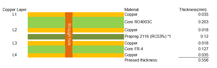
5. PCB Stackup: 4-layer hybrid rigid PCB
6. Type of artwork supplied
Gerber RS-274-X
7. Quality standard
IPC-Class-2
8. Availability
Worldwide
9. Some Typical Applications
- Cellular base station antennas & power amplifiers
- Automotive radar and RF sensor modules
- RF identification hardware
- Direct broadcast satellite LNB devices
- Microwave communication transceiver circuits
10. Rogers RO4003C & Hybrid FR4 Prepreg Copper Clad Laminate Knowledge
Rogers RO4003C laminate is a proprietary woven glass reinforced hydrocarbon/ceramic composite. Rogers RO4003C material provides electrical performance close to PTFE glass substrates while retaining the manufacturability of standard FR4. This Rogers 4003 PCB material does not require special through-hole treatment, suitable for hybrid multilayer PCB construction. RO4003C is non-brominated and not UL 94 V-0 rated.
10.1 Core Electrical & Material Features
- Dk 3.38 ±0.05 @10GHz, thermal coefficient of dielectric constant +40 ppm/°C; Df 0.0027 at 10 GHz
- Low moisture absorption of 0.06%, thermal conductivity of 0.71 W/m/K
- X-axis CTE:11 ppm/°C, Y-axis CTE:14 ppm/°C, Z-axis CTE:46 ppm/°C, closely matched to copper
- High Tg over 280°C, stable performance under PCB lamination and thermal cycling
- 8mil thin RO4003C core supports tight impedance control for RF traces on 4-layer Rogers 4003 PCB
10.2 Stackup Design & Rationality Analysis
The 8mil RO4003C high-frequency core serves as the primary dielectric medium for RF signal transmission within this 4-layer Rogers 4003 hybrid PCB. Thanks to its low dielectric constant and low dissipation factor, the RO4003C core effectively cuts down high-frequency signal attenuation, while the thin dielectric thickness enables precise impedance management to meet strict RF circuit electrical requirements.
The design adopts dual 5mil Tg170 FR4 prepreg to strike a good balance between manufacturing cost and thermal performance. Constructing a full multilayer board entirely with premium high-frequency ceramic laminates would push material costs significantly higher. The Tg170 high-temperature prepreg enhances the board heat resistance and anti-delamination capability, allowing the Rogers 4003 multilayer PCB to withstand multiple SMT reflow cycles during component assembly.
Designers must account for inherent CTE mismatch risks when combining mixed dielectric materials. RO4003C and FR4 feature dissimilar thermal expansion coefficients. Therefore, the heating and cooling profile during lamination requires dedicated process tuning, which helps prevent common defects such as interlayer delamination and board warpage on the finished Rogers 4003 multilayer PCB.
The stackup combination is carefully calculated to achieve the target 0.556mm total laminated thickness. By stacking the 8mil RO4003C core, two sheets of 5mil FR4 prepreg together with specified copper foils, this Rogers 4003 PCB achieves standardized thin-board dimensions with tightly controlled thickness tolerance for mass production.
10.3 Processing & Fabrication Notes
- Hybrid dielectric PCB requires customized lamination cycle to release thermal stress and minimize warpage
- Careful material selection and pre-baking are required before lamination to reduce void and delamination risk
- Suitable for standard FR4 manufacturing workflow, no special PTFE machining required for Rogers 4003 PCB
- SMT process needs to consider hybrid material thermal characteristics and set proper reflow temperature profile
11. Application
4-layer 0.556mm Rogers 4003 PCB is widely applied in cellular base station antenna systems, RF power amplifiers, automotive radar sensors, satellite LNB modules and microwave transceiver hardware. Rogers 4003 multilayer PCB with RO4003C + Tg170 FR4 stackup is a preferred hybrid RF board solution for engineers who need stable high-frequency signal performance while keeping PCB manufacturing cost under control.
12. Product Summary
Rogers 4003 4-layer hybrid dielectric PCB is a rigid multilayer RF circuit board with 8mil RO4003C core plus dual 5mil Tg170 FR4 prepreg, total laminated thickness of 0.556mm. Rogers 4003 hybrid PCB features 0.5oz inner copper, 1oz finished outer copper, green solder mask, white top silkscreen and immersion gold surface finish. This Rogers 4003 PCB undergoes 100% electrical testing before shipment. The mixed stackup of this 4-layer Rogers 4003 PCB achieves the balance between high-frequency electrical performance, mechanical reliability and production cost, widely used in base station antenna, automotive radar and microwave communication systems.
13.RO4003C Properties