



 Home
-
High Temperature PCB
-
Panasonic MEGTRON6 (M6) 14-Layer PCB 2.123mm Impedance-Controlled PCB with ENEPIG Finish For High-Speed Computing & Test Equipment
Home
-
High Temperature PCB
-
Panasonic MEGTRON6 (M6) 14-Layer PCB 2.123mm Impedance-Controlled PCB with ENEPIG Finish For High-Speed Computing & Test Equipment
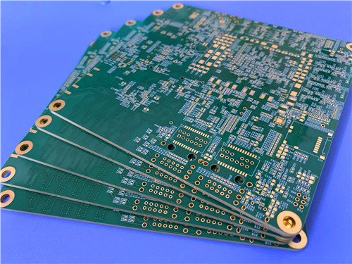
Panasonic MEGTRON6 (M6) 14-Layer PCB 2.123mm Impedance-Controlled PCB with ENEPIG Finish For High-Speed Computing & Test Equipment
Printed Circuit Boards are custom-made products; the images and specifications provided are for reference only.
Panasonic MEGTRON6 PCB is a premium low-loss high-speed laminate series represented by R-5775 core and matching R-5670 prepreg, engineered for complex multi-layer high-speed digital and millimeter-wave circuit designs. MEGTRON6 hydrocarbon-based substrate delivers ultra-stable Dk/Df across wide frequency bands from 1GHz up to 58GHz, paired with outstanding thermal resistance and low Z-axis CTE to eliminate layer separation risks during repeated reflow cycles. MEGTRON6 material supports full FR-4 compatible manufacturing workflow without special plasma pre-treatment for routine production, while offering flexible copper foil selections including standard ED, reverse treated and HVLP foil for different PIM and impedance control demands. With Tg up to 185°C (DSC) and Td reaching 410°C, M6 material maintains stable physical properties under long-duration high-temperature exposure. It is fully compliant with IPC-6012 Class 3 high-reliability standards, perfectly suited for thick 14-layer multi-layer PCBs requiring strict impedance tolerance, micro-via resin plugging and ENEPIG surface finishing for industrial computing, precision test instruments and communication infrastructure hardware.
2. Core Features
- Ultra-low dissipation factor Df 0.002 @1GHz and 0.0037 @13GHz for minimal high-speed signal attenuation
- Stable dielectric constant Dk 3.40 @1GHz with tiny frequency fluctuation up to millimeter wave range
- High thermal performance: Tg 185°C (DSC), Tg 210°C (DMA), Td 410°C, T288 >120min with copper cladding
- Low Z-axis thermal expansion coefficient α1=45ppm/°C below Tg to suppress via barrel cracking
- Full FR-4 compatible fabrication process without special PTFE plasma desmear
- Supports micro-via resin plug & electroplating fill for holes smaller than 0.4mm
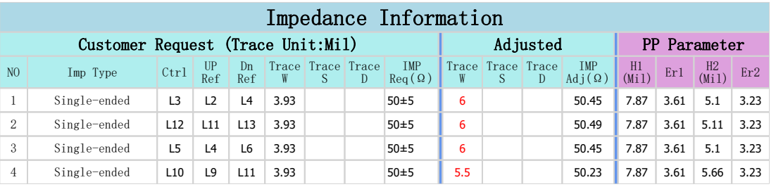
- Strict controlled impedance capability for differential and single-ended high-speed traces
- UL 94 V0 flame retardant certification, RoHS and lead-free assembly compliant
- Multiple laminate thickness and prepreg resin content options for customized 14-layer stackup
- Compatible with ENEPIG, Immersion Gold, OSP and Sn surface finishing processes
3. Key Material Benefits
- Consistent signal integrity across wide temperature and frequency operating windows
- Superior multi-layer lamination stability with minimal dimensional shift during press cycles
- Long T288 delamination resistance for repeated lead-free reflow soldering
- Moderate desmear consumption rate compared to standard FR-4 to simplify hole wall treatment
- Excellent peel strength up to 0.8kN/m with 1oz HVLP copper foil
- Low water absorption rate 0.14% to avoid electrical parameter drift in humid environments
- Optimized drilling characteristics for micro-hole production under 0.4mm diameter
- High-reliability ENEPIG compatibility without lengthy pre-baking restriction for most layouts
4. PCB Construction Details
| Parameter Item | Technical Specification |
| Base Material | Panasonic MEGTRON6 (M6) R-5775 Laminate + R-5670 Prepreg |
| Layer Count | 14 Layers Rigid Multi-Layer PCB |
| Finished Lamination Thickness | 2.123mm |
| Finished Copper Weight All Layers | 1oz (35μm) Uniform Inner & Outer Copper |
| Board Dimensions | 100mm × 98mm = 1PCS |
| Top Solder Mask & Silkscreen | Green Solder Mask, White Silkscreen |
| Bottom Solder Mask & Silkscreen | Green Solder Mask, White Silkscreen |
| Surface Finish | ENEPIG (Electroless Nickel Electroless Palladium Immersion Gold) |
| Via Plating Thickness | 25μm Standard Hole Copper |
| Micro-Via Treatment | Resin Plugged & Electroplating Filled For Holes <0.4mm |
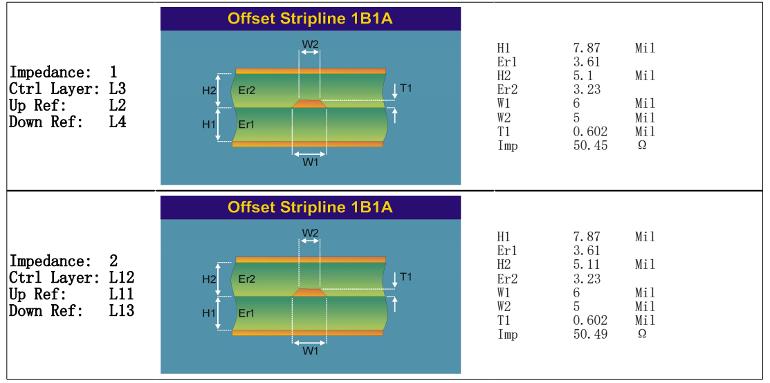
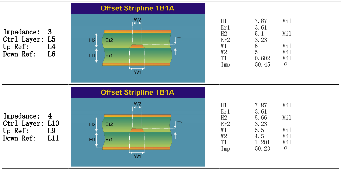
| Electrical Requirement | Strict Controlled Impedance Design |
| Quality Standard | IPC-6012 Class 3 High Reliability Grade |
| Pre-Shipment Inspection | 100% Full Electrical Continuity & Insulation Test |
5. PCB Stackup
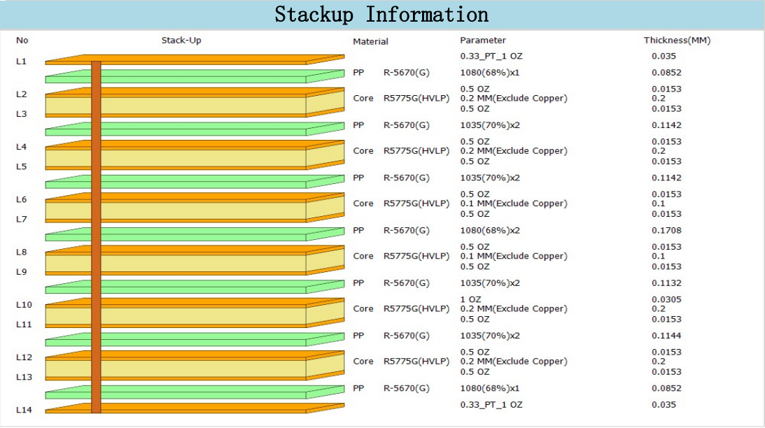
MEGTRON6 14-layer symmetrical multi-layer PCB adopts hybrid stackup built with MEGTRON6 R-5775 core and R-5670 prepreg, all conductive layers equipped with uniform 1oz finished copper. The layered dielectric arrangement balances impedance uniformity and overall 2.123mm finished thickness, with all micro-vias below 0.4mm fully resin plugged and electroplated flat to meet high-density interconnection requirements.
6. PCB Statistics
- Total Components: Customized Per Customer Layout
- Total Pads: Customized Per Customer Layout
- Thru Hole Pads: Customized Per Customer Layout
- Top SMT Pads: Customized Per Customer Layout
- Bottom SMT Pads: Customized Per Customer Layout
- Total Vias: Customized Per Customer Layout
- Total Nets: Customized Per Customer Layout
7. Manufacturing File Format
Production Artwork Standard: Gerber RS-274-X
8. Global Supply Availability
Worldwide Custom Multi-Layer PCB Manufacturing & Delivery Service
9. Typical Application Scenarios
- High-Speed Computing Mainboards & Server Signal Boards
- Precision Microwave & RF Test Measurement Equipment
- 5G/6G Communication Infrastructure Hardware
- Automotive Millimeter Radar Control Modules
- Aerospace High-Reliability Electronic Assemblies
- High-Density HDI Multi-Layer Impedance Controlled Circuits
10. Panasonic MEGTRON6 (M6) Data Sheet Full Technical Introduction
10.1 Core Thermal Properties
- Glass Transition Temp (DSC): 185°C
- Glass Transition Temp (DMA): 210°C
- Thermal Decomposition Temp (Td): 410°C
- T288 Delamination Time (With/Without Copper): >120 Minutes
- Z-axis CTE α1 (<Tg): 45ppm/°C; Z-axis CTE α2 (>Tg): 260ppm
10.2 Core Electrical Performance
- Volume Resistivity: 1×10⁹ MΩ·cm
- Surface Resistivity: 1×10⁸ MΩ
- Dk @1GHz: 3.40; Dk @13GHz:3.34
- Df @1GHz:0.002; Df @13GHz:0.0037
- Test Standard: IPC TM-650, Balanced Circular Disk Resonance Method for 13–58GHz
10.3 Physical Specifications
- Water Absorption Rate: 0.14%
- Peel Strength (1oz HVLP Copper): 0.8kN/m
- Flammability Rating: UL 94 V0
10.4 Standard Laminate & Prepreg Thickness Options
Multiple core mil/mm thickness combinations from 2.0mil (0.050mm) up to 29.5mil (0.750mm), matched R-5670 prepreg with adjustable resin content 56%–77% to support 4–20 layer thick PCB stackup design.
10.5 Compatible Copper Foil Types
Standard ED Copper, Reverse Treated Copper, HVLP Low Profile Copper, Resistive Embedded Foil are all available for MEGTRON6 laminates.
11. Panasonic MEGTRON6 (M6) Complete Process Guideline
11.1 Material Storage Rules
- Laminate sheets must be stored flat in cool dry ambient, avoid bending and surface scratch damage; keep inside original sealed packaging as much as possible.
- R-5670 prepreg storage environment: temperature ≤23°C (73°F), relative humidity ≤50% RH. Long-term storage requires 5°C (41°F) low-temperature cabinet.
- Opened prepreg bags must be fully resealed; cumulative exposure time under standard environment cannot exceed 8 hours total.
11.2 Laminate Surface & Inner Layer Treatment
- Shiny standard ED copper: chemical clean or mechanical scrub process acceptable.
- Reverse treated copper foil: only chemical micro-etch cleaning recommended, mechanical scrub is prohibited.
- Inner layer bond treatment: black oxide, brown oxide or alternative organic peroxide/sulfuric oxide process are all applicable. Verify peel strength if adopting black oxide treatment.
- Post-etch drying: rack bake at 105°C (225°F) for 20–30 minutes to fully eliminate absorbed moisture before lamination.
11.3 Standard Drilling Parameters & Operation Tips
- Spindle speed range controlled to maintain linear velocity 100–150m/min for all drill sizes.
- Recommended entry sheet: lubricated aluminum LE sheet; high helix angle carbide drill bits preferred.
- Small holes under 0.4mm adopt peck drilling to reduce resin smear and extend bit service life.
- Reference parameter range: 0.20mm–0.90mm drill bits, spindle speed 53–160krpm, hit count 700–2000 hits per drill, chipload adjusted from 10–45μ/rev according to diameter.
- Target positioning accuracy of M6 material reaches below 47.2μm under standard stack condition.
11.4 Multi-Layer Lamination Process Specification
- Heating rate controlled at 2.0–4.0°C/min; maintain product core temperature over 185°C for minimum 75 minutes.
- Standard pressing pressure range: 3.0–4.0MPa, increase pressure by 0.5MPa and hold 20 minutes at mid heating stage.
- Vacuum limit max 100torr (13.3kPa), stop vacuum pumping at 30min from start time when temperature hits 90–130°C.
- Adjust lamination cycle based on total stack thickness and layer quantity for 14-layer thick boards.
11.5 Desmear Treatment Guidance
- Permanganate chemical desmear: M6 material resin weight loss is lower than conventional FR-4, extend processing time to double standard FR-4 cycle. Two available processes: alkaline swelling + permanganate etch or organic solvent swelling + permanganate etch.
- Plasma desmear: processing time cut to half of standard FR-4 parameters to avoid excessive substrate erosion.
- Hybrid FR4+M6 stack: plasma half-cycle first, then permanganate desmear without swelling step continuously.
11.6 Surface Finishing Compatibility
- Compatible finishes: Silver Plating, Tin Plating, Direct Immersion Gold, OSP.
- ENEPIG Process Notice: Pre-bake 150°C for 5 hours or store 1 week at room temperature before nickel plating to guarantee stable adhesion, adjust holding time based on equipment circulation & bubbling performance.
11.7 Pre-Use & Safety Notes
- Conduct full design performance test to verify material fitness before mass production switch.
- Sign mutual delivery specification agreement to clarify technical standards prior to formal order.
- Product appearance color may slightly differ from reference images; material specs can be revised without prior notice for product upgrade.
- MEGTRON6 series materials exclusively for electronic circuit board manufacturing, not allowed for other industrial usages.
12.DataSheet
| Part Number | R-5775(K)/R-5670(K) | R-5775(N)/R-5670(N) | R-5775(G)/R-5775(G) |
| Tg (DSC) | 185 °C | 185 °C | 185 °C |
| Tg (DMA) | 210 °C | 210 °C | 210°C |
| Td (Thermal Decomposition) (°C) | 410 °C | 410 °C | 410 °C |
| T288 (Without Cu) (min) | >120 min | >120 min | >120 min |
| T288 (With Cu) (min) | >120 min | >120 min | >120 min |
| CTE-Y | 14-16 ppm/°C | 14-16 ppm/°C | 14-16 ppm/°C |
| CTE-Y | 14-16 ppm/°C | 14-16 ppm/°C | 14-16 ppm/°C |
| CTE-Z | 45 ppm/°C | 45 ppm/°C | 45 ppm/°C |
| CTE α2 Z-axis: Test Method IPC-TM-650 2.4.24; Condition A (ppm/℃) | 260 ppm/°C | 260 ppm/°C | 260 ppm/°C |
| Thermal Conductivity, (W/m・K) | 0.42 W/m · K | 0.42 W/m · cm | 0.42 W/m · cm |
| Volume Resistivity (MΩ・cm) | 1 x 10⁹ MΩ · cm | 1 x 10⁹ MΩ · cm | 1 x 10⁹ MΩ · cm |
| Surface Resistivity (mΩ) | 1 x 10⁸ MΩ | 1 x 10⁸ MΩ | 1 x 10⁸ MΩ |
| Dielectric Constant (Dk) @ 1Ghz; Test Method IPC-TM-650; Condition C-24/23/50 | 3.4 | 3.4 | 3.4 |
| Dielectric Constant (Dk) @ 10Ghz; Test Method IPC-TM-650; Condition C-24/23/50 | —— | —— | —— |
| Dielectric Constant (Dk) @ 12Ghz; Test Method Balanced-type Circular Disk Resonator; Condition C-24/23/50 | 3.4 | 3.4 | 3.4 |
| Df at 1 GHz | 0.002 | 0.002 | 0.002 |
| Df at 10 GHz | —— | —— | —— |
| Df at 12 GHz | 0.004 | 0.004 | 0.004 |
| Water Absorption (%) | 0.14% | 0.14% | 0.14% |
| Poisson's Ratio | 0.2 | 0.2 | 0.2 |
| Flexural Warp (MD) (GPa) | 19 GPa | 19 GPa | 19 GPa |
| Flexural Fill (TD) (GPa) | 18 GPa | 18 GPa | 18 GPa |
| Peel Strength (1 Oz. Cu) (kN/m) | 0.8 (Cu:H-VLP) kN/m | 0.8 (Cu:H-VLP) kN/m | 0.8 (Cu:H-VLP) kN/m |
| Flammability | 94V-0 | 94V-0 | 94V-0 |