



 Home
-
High frequency PCB
-
TFA294 2-Layer PTFE Ceramic Composite PCB 80mil TFA294 Laminate with OSP Finish For Communication and Signal Sensing Systems
TFA294 2-Layer PTFE Ceramic Composite PCB 80mil TFA294 Laminate with OSP Finish For Communication and Signal Sensing Systems
Printed Circuit Boards are custom-made products; the images and specifications provided are for reference only.
1.Introduction
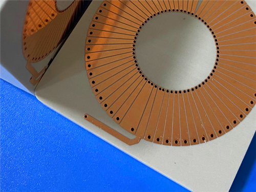
TFA294 PCB is a high-reliability high frequency printed circuit board built on fiberglass-free PTFE ceramic composite dielectric substrate. TFA series substrate dielectric material consists of PTFE resin and ceramic fillers, manufactured with a novel sheet forming process instead of the conventional glass fabric impregnation method. The special lamination process endows TFA294 PCB with excellent electrical, thermal and mechanical properties. TFA294 high frequency PCB removes fiberglass weave effect during electromagnetic wave propagation thanks to homogeneous nano-ceramic mixed with PTFE resin. TFA294 substrate minimizes X/Y/Z anisotropy and maintains low thermal expansion coefficient matching copper foil together with stable dielectric temperature performance. The TFA family offers multiple dielectric constant options including 2.94, 3.0, 6.15 and 10.2, corresponding to part numbers TFA294, TFA300, TFA615, TFA1020. TFA294 PCB serves as a reliable alternative to comparable imported high-frequency materials.
2.Features
- Dielectric constant (Dk) of 2.94 at 10GHz
- Dissipation factor of 0.0010 at 10GHz and 20 GHz, 0.0012 at 40 GHz
- Low TCDK at -5 ppm/°C, ranging from -55°C to 150°C
- CTE x-axis of 18 ppm/°C, CTE y-axis of 18 ppm/°C, CTE z-axis of 32 ppm/°C, -55°C to 288°C
- Thermal conductivity of 0.59 W/mk
- Moisture absorption of 0.03%
- UL 94-V0 flame retardant rating
- 3.Benefits
- Eliminates fiberglass weave effect for consistent electromagnetic transmission
- Minimal material anisotropy for stable high-frequency performance
- Low thermal expansion coefficient closely matched to copper foil
- Stable dielectric constant over broad temperature and frequency ranges
- Low moisture absorption for long-term service reliability
- High-reliability performance for signal transmission and sensing hardware
- 4.PCB Construction details
| Item | Specification |
| Board dimensions | 49mm x 90.3 mm=1PCS, +/- 0.15mm |
| Minimum Trace/Space | 6/7 mils |
| Minimum Hole Size | 0.35mm |
| Blind vias | No |
| Finished board thickness | 2.1mm |
| Finished Cu weight | 1oz (1.4 mils) outer layers |
| Via plating thickness | 20 μm |
| Surface finish | OSP |
| Top Silkscreen | No |
| Bottom Silkscreen | No |
| Top Solder Mask | No |
| Bottom Solder Mask | No |
| Pre-shipment test | 100% Electrical test used prior to shipment |
5.PCB Stackup: 2-layer rigid PCB
- Copper_layer_1 - 35 μm
- TFA294 Core - 2.03 mm (80mil)
- Copper_layer_2 - 35 μm
- PCB Statistics
- Components: 16
- Total Pads: 31
- Thru Hole Pads: 18
- Top SMT Pads: 13
- Bottom SMT Pads: 0
- Vias: 7
- Nets: 2
6.Type of artwork supplied: Gerber RS-274-X
7.Quality standard: IPC-Class-2
8.Some Typical Applications
- Aerospace equipment, space, in-cabin equipment, aircraft
- Microwaves, antennas, phase-sensitive antennas
- Early warning radars, airborne radars
- Phased array antennas, beamforming networks
- Satellite communications, navigation
- Power amplifiers
9.Availability: Worldwide
10.TFA & TFA294 PTFE Ceramic Composite Copper Clad Laminate Knowledge
The TFA series is an aerospace-grade, fiberglass-free PTFE ceramic composite copper clad laminate developed as a high-reliability alternative to premium imported high-frequency substrates. Unlike traditional laminates made by impregnating fiberglass cloth, TFA CCL blends nano-ceramic powder uniformly with high-purity PTFE resin to form sheets, followed by precision lamination. This fiberglass-free design eliminates fiberglass weave distortion and reduces X/Y/Z material anisotropy for stable high-frequency signal transmission.
10.1Core Electrical & Material Features
- Tight dielectric constant tolerance and consistent batch performance; TFA294 features stable Dk 2.94
- Ultra-low dielectric loss, supports operating frequencies up to 77GHz, covering millimeter-wave bands
- Stable dielectric and phase performance from -55°C to 150°C
- Excellent radiation resistance and low outgassing performance, meets aerospace vacuum standards
- Copper foil matched thermal expansion coefficient, ultra-low water absorption
- UL 94-V0 flame retardant rating
10.2 Processing & Structural Advantages
- Compatible with standard PTFE PCB manufacturing processes
- Supports multi-layer boards, backplanes, dense vias and fine trace circuits
- Standard low-roughness RTF copper foil; optional rolled copper, copper base and aluminum base structures
- TFA294 supports embedded 50Ω resistance copper foil for integrated resistance film substrates
10.3 Application Scenarios
Aerospace electronics, radar systems, phased array antennas, satellite communication, microwave circuits and high-frequency power amplifiers
11.Product Summary
TFA294 2-Layer high frequency PCB is a rigid printed circuit board fabricated on 80mil TFA294 PTFE ceramic composite copper clad laminate. TFA294 PCB features OSP surface finish, no solder mask and no silkscreen on both sides. TFA294 PCB undergoes 100% electrical testing before shipment to guarantee circuit integrity. TFA294 PCB eliminates fiberglass weave effect and offers stable dielectric performance for wireless communication and precision signal sensing systems.
12.TFA294 DataSheet
| Product Property | Test Condition | Unit | Typical Value |
| Dielectric Constant (Typical) | 10 GHz | / | 2.94 |
| Dielectric Constant (Design) | 10 GHz | / | 2.94 |
| Dielectric Constant Tolerance | / | / | ±0.04 |
| Dissipation Factor (Typical) | 10 GHz | / | 0.001 |
| Dissipation Factor (Typical) | 20 GHz | / | 0.001 |
| Dissipation Factor (Typical) | 40 GHz | / | 0.0012 |
| Thermal Coefficient of Dielectric Constant | -55 °C ~ 150 °C | ppm/°C | -5 |
| Copper Peel Strength | 1 oz RTF Foil | N/mm | > 1.6 |
| Volume Resistivity | Ambient Condition | MΩ·cm | ≥ 5×10⁷ |
| Surface Resistivity | Ambient Condition | MΩ | ≥ 5×10⁷ |
| Dielectric Strength (Z-axis) | 5KW, 500V/s | KV/mm | > 35 |
| Breakdown Voltage (XY-axis) | 5KW, 500V/s | KV | > 40 |
| Coefficient of Thermal Expansion (X, Y-axis) | -55 °C ~ 288 °C | ppm/°C | 18, 18 |
| Coefficient of Thermal Expansion (Z-axis) | -55 °C ~ 288 °C | ppm/°C | 32 |
| Thermal Stress | 260 °C, 10s, 3 cycles | / | No Delamination |
| Water Absorption | 20±2 °C, 24h | % | 0.03 |
| Density | Ambient Temperature | g/cm³ | 2.14 |
| Continuous Operating Temperature | Temperature & Humidity Chamber | °C | -55 ~ +260 |
| Thermal Conductivity (Z-axis) | / | W/(m·K) | 0.59 |
| Flammability | / | UL-94 | V-0 |
| Td (Onset Temperature) | / | °C | 498 |
| Material Composition | / | / | PTFE + Ceramic(A tiny amount of glass fabric will be added when dielectric thickness exceeds 1.5mm) |