


 Home
-
F4B PCB
-
F4BME220 2-Layer 0.1mm Ultra-Thin Rigid PCB PTFE Laminate with Green Solder Mask for Low PIM RF Radar and Antenna
Home
-
F4B PCB
-
F4BME220 2-Layer 0.1mm Ultra-Thin Rigid PCB PTFE Laminate with Green Solder Mask for Low PIM RF Radar and Antenna
F4BME220 2-Layer 0.1mm Ultra-Thin Rigid PCB PTFE Laminate with Green Solder Mask for Low PIM RF Radar and Antenna
Printed Circuit Boards are custom-made products; the images and specifications provided are for reference only.
1. Product Introduction
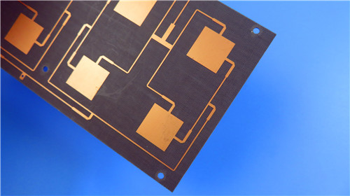
F4BME220 2-Layer ultra-thin 0.1mm high frequency PCB is a premium low-PIM microwave circuit board belonging to the upgraded F4BME series PTFE fiberglass laminate family. Optimized for high-reliability RF and microwave working scenarios, F4BME220 rigid PCB adopts high-performance F4BME220 substrate with professional RTF reverse-treated copper foil, delivering excellent passive intermodulation performance, ultra-low conductor loss and precise circuit printing capability. Compared with traditional F4B series materials, F4BME220 laminate features adjustable wide-range dielectric constant, lower high-frequency dissipation factor, higher insulation resistance and superior long-term operational stability. F4BME220 custom PCB is finished with immersion gold surface treatment, green top solder mask and white top silkscreen, supporting 5/8 mils fine trace and space fabrication. Manufactured in accordance with IPC-Class-2 industrial standards and 100% electrically tested before shipment, the board combines aerospace-grade radiation resistance, low-outgassing characteristics and commercial mass-production cost advantages, serving as a high-quality replacement for imported high-frequency substrates for radar, phased array antenna, satellite communication and base station antenna systems worldwide.
2. Core Product Features
- Adjustable Wide-Range Dielectric Constant: F4BME220 high-frequency laminate supports flexible dielectric constant customization ranging from 2.17 to 3.0, with tailored DK values available for special high-frequency circuit designs, fully adapting to diverse microwave impedance matching requirements.
- Ultra-Low High-Frequency Dielectric Loss: Optimized PTFE and fiberglass composite formula effectively suppresses high-frequency signal attenuation, achieving ultra-low dissipation performance and ensuring high-efficiency, high-purity signal transmission for long-running RF and microwave devices.
- Excellent Low-PIM Performance: Equipped with standard RTF reverse-treated copper foil, the circuit board eliminates intermodulation interference caused by conventional copper foil, delivering superior PIM stability for phase-sensitive antenna and radar systems.
- Aerospace-Grade Environmental Reliability: Inherits the F4BME series’ outstanding radiation resistance and ultra-low outgassing properties, meeting space and aerospace extreme environment standards, while maintaining stable electrical and physical properties under complex working conditions.
- High-Precision Fabrication Adaptability: Supports 5/8 mils fine trace/space and 0.25mm ultra-small hole processing, with excellent dimensional stability and low thermal drift, suitable for compact and high-precision microwave circuit integration.
3. Product Performance Benefits
- Differentiated Copper Foil Optimization: Different from ED copper foil-based F4BM substrates for ordinary scenarios, F4BME220 adopts professional RTF reverse-treated copper foil, realizing lower conductor loss, more uniform circuit line width and excellent PIM performance for high-sensitive RF equipment.
- Tunable Structural Stability & Loss Balance: Precisely adjusts the PTFE-to-fiberglass ratio to balance low dielectric loss and dimensional stability. Reasonable glass fiber content optimizes thermal expansion coefficient and temperature drift characteristics, reducing processing deformation and thermal stress damage.
- Cost-Effective Mass Production: Supports multiple standard panel sizes to minimize raw material waste and lower overall manufacturing costs. Compatible with mature PTFE PCB production processes, it achieves stable commercial mass production with outstanding cost-performance ratio.
- Diversified Surface Process Adaptability: Matched with immersion gold finishing, green solder mask and white silkscreen processes, the board features clear circuit identification, excellent oxidation resistance and stable assembly performance, adapting to various SMT and through-hole assembly processes.
- Wide-Scenario Application Compatibility: Integrates aerospace-grade extreme environmental adaptability and commercial-grade cost advantages, covering high-end military radar, satellite communication and civil base station antenna mass production scenarios.
4. PCB Construction Details
| Parameter Item | Technical Specification |
| Base Material | F4BME220 High-Frequency PTFE Fiberglass Laminate |
| Layer Count | 2-Layers |
| Board Dimensions | 79mm x 65.3mm (1 Piece), Tolerance +/- 0.15mm |
| Minimum Trace/Space | 5/8 mils |
| Minimum Hole Size | 0.25mm |
| Blind Vias | No Blind Vias Design |
| Finished Board Thickness | 0.1mm Ultra-Thin Rigid Board |
| Outer Layer Finished Copper Weight | 1 OZ (1.4 mils) |
| Via Plating Thickness | 20 μm |
| Surface Finish | Immersion Gold |
| Top Silkscreen | White Silkscreen |
| Bottom Silkscreen | No Silkscreen |
| Top Solder Mask | Green Solder Mask |
| Bottom Solder Mask | No Solder Mask |
| Pre-Shipment Test | 100% Electrical Testing |
5. PCB Stackup Structure
F4BME220 2-Layer rigid PCB adopts standardized F4BME220 core dielectric stackup structure, with uniform layer distribution and stable high-frequency electrical performance, fully meeting precision microwave circuit design requirements:
1. Copper_layer_1: 35 μm
2. F4BME220 Core Substrate: 0.1mm
3. Copper_layer_2: 35 μm
6. PCB Statistical Parameters
- Total Components: 23
- Total Pads: 26
- Thru Hole Pads: 14
- Top SMT Pads: 12
- Bottom SMT Pads: 0
- Total Vias: 37
- Total Nets: 2
7. Production & Quality Standards
- Artwork Supply Format: Gerber RS-274-X
- Manufacturing Quality Standard: IPC-Class-2
- Supply Scope: Worldwide Supply & Service
8. Typical Application Scenarios
Thanks to adjustable dielectric constant, ultra-low high-frequency loss, excellent low-PIM performance and aerospace-grade environmental stability, F4BME220 2-Layer ultra-thin PCB is widely applicable in high-precision high-frequency electronic fields. F4BME220 2-Layer high-frequency PCB is commonly used for microwave circuits, RF components, military and civil radar systems, phase shifters, passive components, power dividers, couplers, combiners, antenna feed networks, phased array antennas, satellite communication systems and 4G/5G base station antenna equipment.
9. F4BME220 Copper Clad Laminate (CCL) Knowledge
9.1 F4BM & F4BME Series Laminate Overview
F4BME220 Copper Clad Laminate is a high-reliability ultra-thin substrate grade under the upgraded F4BM/F4BME PTFE fiberglass laminate series. Manufactured with scientifically proportioned woven fiberglass fabric, high-purity polytetrafluoroethylene resin and PTFE film through strictly controlled pressing processes, this advanced PCB material achieves comprehensive performance upgrades over traditional F4B series substrates, featuring wider adjustable dielectric constant range, lower dissipation factor, higher insulation resistance and superior long-term operational stability, capable of full replacement of imported international equivalent microwave laminates.
The F4BM and F4BME series share identical dielectric core formulations but adopt differentiated copper foil configurations for targeted application scenarios. The F4BM version uses cost-effective ED copper foil for conventional high-frequency circuits without strict PIM requirements, while the upgraded F4BME series including F4BME220 is equipped with premium reverse-treated RTF copper foil, delivering outstanding passive intermodulation suppression, precise circuit trace control and reduced conductor loss for high-sensitive RF designs.
 F4BME220.jpg)
9.2 Core Material Properties & Tunable Mechanism
The F4BM and F4BME material series support precise dielectric constant adjustment by modifying the mixing ratio of PTFE resin and fiberglass cloth. This unique tuning mechanism perfectly balances low dielectric loss and structural dimensional stability. A higher fiberglass proportion effectively optimizes thermal expansion coefficient, reduces temperature drift and improves overall rigidity, while bringing a moderate and controllable increase in dielectric loss, meeting diversified design demands of commercial and industrial high-frequency circuits. As a specialized grade, F4BME220 further optimizes formula consistency, providing more stable and uniform dielectric performance for ultra-thin high-precision PCB fabrication.
9.3 Key Laminate Advantages
- Customizable Dielectric Parameters: Supports continuous DK adjustment from 2.17 to 3.0 with custom-tailored values available, adapting to various microwave circuit impedance matching and design specifications.
- Professional Low-PIM Performance: RTF reverse-treated copper foil configuration eliminates signal interference and intermodulation distortion, ideal for phase-sensitive antenna and radar system applications.
- Cost-Optimized Production: Multiple standard panel sizes minimize material waste and manufacturing costs, supporting large-scale commercial mass production with excellent cost-performance.
- Aerospace-Grade Environmental Adaptability: Excellent radiation resistance and ultra-low outgassing performance meet space and aerospace extreme environment testing standards, suitable for high-reliability aerospace electronic equipment.
10. DataSheet
| Property | DIRECTION | TEST CONDITIONS | UNITS | TYPICAL VALUES (F4BME220) |
| Dielectric Constant (Typical Value) | - | 10 GHz | - | 2.2 |
| Dielectric Constant Tolerance | - | - | - | ±0.04 |
| Dissipation Factor (Typical Value) | - | 10 GHz | - | 0.001 |
| Dissipation Factor (Typical Value) | - | 20 GHz | - | 0.0014 |
| Thermal Coefficient of Dielectric Constant | - | -55℃~150℃ | ppm/℃ | -142 |
| Copper Peel Strength | - | 1 OZ F4BM copper | N/mm | >1.8 |
| Copper Peel Strength | - | 1 OZ F4BME copper | N/mm | >1.6 |
| Volume Resistivity | - | Normal condition | MΩ·cm | ≥6×10⁶ |
| Surface Resistivity | - | Normal condition | MΩ | ≥1×10⁶ |
| Dielectric Strength (Z-direction) | Z | 5KW, 500V/s | KV/mm | >23 |
| Breakdown Voltage (XY-direction) | XY | 5KW, 500V/s | KV | >30 |
| Coefficient of Thermal Expansion | XY | -55℃~288℃ | ppm/℃ | 25~34 |
| Coefficient of Thermal Expansion | Z | -55℃~288℃ | ppm/℃ | 240 |
| Thermal Stress Resistance | - | 260℃, 10s, 3 cycles | - | No delamination |
| Moisture Absorption | - | 20±2℃, 24 h | % | ≤0.08 |
| Density | - | Ambient temperature | g/cm³ | 2.18 |
| Long-Term Operating Temperature | - | Temperature chamber | ℃ | -55~+260 |
| Thermal Conductivity | Z | - | W/(m·K) | 0.24 |
| PIM Value | - | Only for F4BME | dBc | ≤-159 |
| Flame Retardancy | - | - | UL-94 | V-0 |
| Material Composition | - | - | - | PTFE, glass fabric |
| Matching Copper Specification | - | - | - | F4BM matches ED copper foil; F4BME matches reversed RTF copper foil |