

 Home
-
Taconic PCB
-
Taconic TSM-DS3 High Frequency PCB Low Loss and High Thermal Conductivity for High-power Applications
Home
-
Taconic PCB
-
Taconic TSM-DS3 High Frequency PCB Low Loss and High Thermal Conductivity for High-power Applications
Taconic TSM-DS3 High Frequency PCB Low Loss and High Thermal Conductivity for High-power Applications
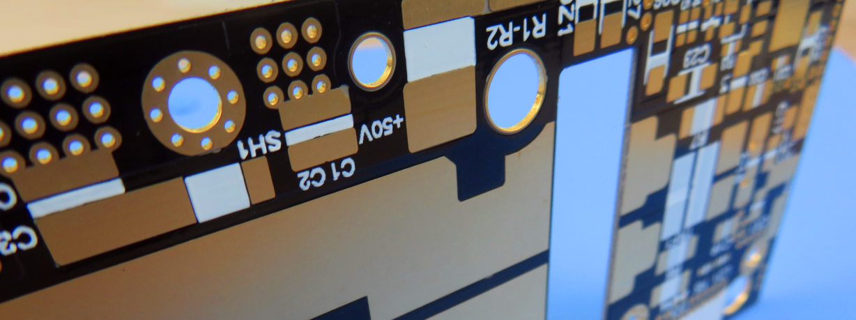
Printed Circuit Boards are custom-made products; the images and specifications provided are for reference only.
Material Introduction
Taconic TSM-DS3 PCB is a high-performance, thermally stable printed circuit board material engineered for demanding high-frequency applications. It features industry-leading low-loss characteristics, demonstrated by an exceptionally low dissipation factor (DF) of 0.0011 at 10 GHz. This material provides outstanding predictability and consistency, rivaling the performance of the best fiberglass-reinforced epoxy laminates.
A key differentiator for TSM-DS3 PCB is its unique composition. As a ceramic-filled, reinforced material with a very low fiberglass content (approximately 5%), it combines superior electrical properties with the manufacturability needed for large-format, complex multilayer boards. This makes it an ideal substrate for challenging designs.
TSM-DS3 excels in high-power applications due to its high thermal conductivity (TC) of 0.65 W/m·K. This property allows the material to effectively draw heat away from critical components on the board, ensuring reliable performance and preventing overheating in power-intensive scenarios.
Furthermore, TSM-DS3 is formulated with a very low coefficient of thermal expansion (CTE). This ensures exceptional dimensional stability during rigorous thermal cycling, guaranteeing long-term reliability and performance consistency even in environments with extreme temperature fluctuations.
Features
1.TSM-DS3 offers an industry-leading dissipation factor (DF) of 0.0011 at 10GHz
2. With high thermal conductivity, TSM-DS3 effectively conducts heat away from heat sources.
3.The material has a low fiberglass content of approximately 5%.
4.TSM-DS3 exhibits dimensional stability comparable to epoxy materials.
5. It enables the fabrication of large format, high layer count printed wiring boards (PWBs) with complex designs.
6. The material allows for the successful construction of complex PCBs with high yield and consistent performance.
7. TSM-DS3 maintains stable dielectric constant (DK) within +/- 0.25 across a wide temperature range (-30 °C to 120 °C).
8. It is compatible with resistor foils, expanding its range of applications.
.jpg)
Typical Applications
TSM-DS3 finds application in various fields, including:
- Couplers
- Phased Array Antennas
- Radar Manifolds
- mmWave Antennas
- Oil Drilling
- Semiconductor / Automatic Test Equipment (ATE) Testing
Our PCB Capability (TSM-DS3)
| PCB Capability (TSM-DS3) | |
| PCB Material: | Ceramic-filled Woven Fiberglass PTFE Laminates |
| Designation: | TSM-DS3 |
| Dielectric constant: | 3 +/-0.05 |
| Dissipation factor | 0.0011 |
| Layer count: | Single Sided, Double Sided, Multi-layer PCB, Hybrid PCB |
| Copper weight: | 1oz (35µm), 2oz (70µm) |
| Dielectric thickness | 5mil (0.127mm), 10mil (0.254mm), 20mil (0.508mm), 30mil (0.762mm), 60mil (1.524mm), 90mil (2.286mm) |
| PCB size: | ≤400mm X 500mm |
| Solder mask: | Green, Black, Blue, Yellow, Red etc. |
| Surface finish: | Immersion gold, HASL, Immersion silver, Immersion tin, ENEPIG, OSP, Bare copper, Pure gold etc.. |
TSM-DS3 Typical Values
| Property | Test Method | Unit | TSM-DS3 | Unit | TSM-DS3 |
| Dk | IPC-650 2.5.5.3 | 3.00 | 3.00 | ||
| TcK (-30 to 120 °C) | IPC-650 2.5.5.5.1 (Modified) | ppm | 5.4 | ppm | 5.4 |
| Df | IPC-650 2.5.5.5.1 (Modified) | 0.0011 | 0.0011 | ||
| Dielectric Breakdown | IPC-650 2.5.6 (ASTM D 149) | kV | 47.5 | kV | 47.5 |
| Dielectric Strength | ASTM D 149 (Through Plane) | V/mil | 548 | V/mm | 21,575 |
| Arc Resistance | IPC-650 2.5.1 | Seconds | 226 | Seconds | 226 |
| Moisture Absorption | IPC-650 2.6.2.1 | 0 | 0.07 | 0 | 0.07 |
| Flexural Strength (MD) | ASTM D 790/ IPC-650 2.4.4 | psi | 11,811 | N/mm2 | 81 |
| Flexural Strength (CD) | ASTM D 790/ IPC-650 2.4.4 | psi | 7,512 | N/mm2 | 51 |
| Tensile Strength (MD) | ASTM D 3039/IPC-650 2.4.19 | psi | 7,030 | N/mm2 | 48 |
| Tensile Strength (CD) | ASTM D 3039/IPC-650 2.4.19 | psi | 3,830 | N/mm2 | 26 |
| Elongation at Break (MD) | ASTM D 3039/IPC-650 2.4.19 | 0 | 1.6 | 0 | 1.6 |
| Elongation at Break (CD) | ASTM D 3039/IPC-650 2.4.19 | 0 | 1.5 | 0 | 1.5 |
| Young’s Modulus (MD) | ASTM D 3039/IPC-650 2.4.19 | psi | 973,000 | N/mm2 | 6,708 |
| Young’s Modulus (CD) | ASTM D 3039/IPC-650 2.4.19 | psi | 984,000 | N/mm2 | 6,784 |
| Poisson’s Ratio (MD) | ASTM D 3039/IPC-650 2.4.19 | 0.24 | 0.24 | ||
| Poisson’s Ratio (CD) | ASTM D 3039/IPC-650 2.4.19 | 0.20 | 0.20 | ||
| Compressive Modulus | ASTM D 695 (23。C) | psi | 310,000 | N/mm2 | 2,137 |
| Flexural Modulus (MD) | ASTM D 790/IPC-650 2.4.4 | kpsi | 1,860 | N/mm2 | 12,824 |
| Flexural Modulus (CD) | ASTM D 790/IPC-650 2.4.4 | kpsi | 1,740 | N/mm2 | 11,996 |
| Peel Strength (CV1) | IPC-650 2.4.8 Sec 5.2.2 (TS) | lbs/in | 8 | N/mm | 1.46 |
| Thermal Conductivity (unclad) | ASTM F 433/ASTM 1530-06 | W/M*K | 0.65 | W/M*K | 0.65 |
| Dimensional Stability (MD) | IPC-650 2.4.39 Sec. 5.4 (After Bake) | mils/in. | 0.21 | mm/M | 0.21 |
| Dimensional Stability (CD) | IPC-650 2.4.39 Sec. 5.4 (After Bake) | mils/in. | 0.20 | mm/M | 0.20 |
| Dimensional Stability (MD) | IPC-650 2.4.39 Sec. 5.5 (TS) | mils/in. | 0.15 | mm/M | 0.15 |
| Dimensional Stability (CD) | IPC-650 2.4.39 Sec. 5.5 (TS) | mils/in. | 0.10 | mm/M | 0.10 |
| Surface Resistivity | IPC-650 2.5.17.1 Sec. 5.2.1 (ET) | Mohms | 2.3 x 10^6 | Mohms | 2.3 x 10^6 |
| Surface Resistivity | IPC-650 2.5.17.1 Sec. 5.2.1 (HC) | Mohms | 2.1 x 10^7 | Mohms | 2.1 x 10^7 |
| Volume Resistivity | IPC-650 2.5.17.1 Sec. 5.2.1 (ET) | Mohms/cm | 1.1 x 10^7 | Mohms/cm | 1.1 x 10^7 |
| Volume Resistivity | IPC-650 2.5.17.1 Sec. 5.2.1 (HC) | Mohms/cm | 1.8 x 10^8 | Mohms/cm | 1.8 x 10^8 |
| CTE (x axis) (RT to 125ºC) | IPC-650 2.4.41/TMA | ppm/ºC | 10 | ppm/ºC | 10 |
| CTE (y axis) (RT to 125ºC) | IPC-650 2.4.41/TMA | ppm/ºC | 16 | ppm/ºC | 16 |
| CTE (z axis) (RT to 125ºC) | IPC-650 2.4.41/TMA | ppm/ºC | 23 | ppm/ºC | 23 |
| Density (Specific Gravity) | ASTM D 792 | g/cm3 | 2.11 | g/cm3 | 2.11 |
| Hardness | ASTM D 2240 (Shore D) | 79 | 79 | ||
| Td (2% Weight Loss) | IPC-650 2.4.24.6 (TGA) | ºC | 526 | ºC | 526 |
| Td (5% Weight Loss) | IPC-650 2.4.24.6 (TGA) | ºC | 551 | ºC | 551 |