

 Home
-
Rigid Flex PCB
-
Rigid-Flex PCB for Wireless Security Systems 3-Layer High Tg170 FR-4 Polyimide Board with Immersion Tin Finish
Home
-
Rigid Flex PCB
-
Rigid-Flex PCB for Wireless Security Systems 3-Layer High Tg170 FR-4 Polyimide Board with Immersion Tin Finish
Rigid-Flex PCB for Wireless Security Systems 3-Layer High Tg170 FR-4 Polyimide Board with Immersion Tin Finish
Printed Circuit Boards are custom-made products; the images and specifications provided are for reference only.
General Description
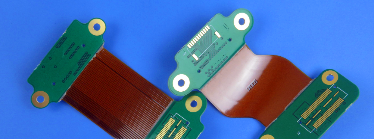
This innovative 3-layer rigid-flex PCB is specifically engineered for wireless security system applications, combining Tg170 FR-4 rigid sections with flexible polyimide materials. The rigid portions maintain a 1.6mm thickness while the flexible areas provide essential bend capability for compact, three-dimensional packaging solutions. Manufactured using high-quality Shengyi base laminates, this rigid-flex circuit board features immersion tin surface finish and green solder mask for enhanced durability and reliable performance.
Produced in strict compliance with IPC 6012 Class 2 standards and utilizing provided Gerber data, this rigid-flex PCB delivers optimal reliability for demanding wireless security applications where space constraints, mechanical flexibility, and consistent electrical performance are critical requirements. The unique combination of rigid and flexible sections allows for innovative product designs while maintaining the structural integrity needed for security system environments.
.jpg)
PCB Specifications
| Size of Flexible PCB | 91.5X 105.3mm | ||||||||||
| Number of Layers | 3 | ||||||||||
| Board Type | Rigid-flex PCB | ||||||||||
| Board Thickness | 1.6mm | ||||||||||
| Board Material | Polyimide (PI) 25µm +FR-4 | ||||||||||
| Board Material Supplier | Shengyi | ||||||||||
| Tg Value of Board Material | 135℃ | ||||||||||
| PTH Cu thickness | ≥20 µm | ||||||||||
| Inner Iayer Cu thicknes | 35 µm | ||||||||||
| Surface Cu thickness | 35 µm | ||||||||||
| Coverlay Colour | Yellow / Green Solder mask | ||||||||||
| Number of Coverlay | 2 | ||||||||||
| Thickness of Coverlay | 25 µm | ||||||||||
| Stiffener Material | NO | ||||||||||
| Stiffener Thickness | N/A | ||||||||||
| Type of Silkscreen Ink | IJR-4000 MW300 | ||||||||||
| Supplier of Silkscreen | TAIYO | ||||||||||
| Color of Silkscreen | White | ||||||||||
| Number of Silkscreen | 1 | ||||||||||
| Peeling test of Coverlay | No peelable | ||||||||||
| Legend Adhesion | 3M 90℃ No peeling after Min. 3 times test | ||||||||||
| Surface Finish | Immersion Tin | ||||||||||
| Thickness of Surface Finish | Tin: 0.8-1.5µm | ||||||||||
| RoHS Required | Yes | ||||||||||
| Famability | 94-V0 | ||||||||||
| Thermal Shock Test | Pass, -25℃±125℃, 1000 cycles. | ||||||||||
| Thermal Stress | Pass, 300±5℃,10 seconds, 3 cycles. No delamination, no blistering. | ||||||||||
| Function | 100% Pass electrical test | ||||||||||
| Workmanship | Compliance with IPC-A-600H & IPC-6013C Class 2 | ||||||||||
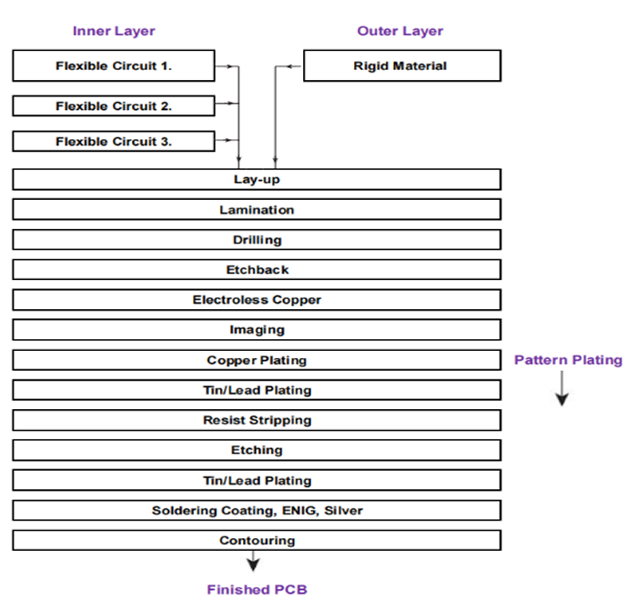
Processes
A simplified flow diagram is shown below.
Features and benefits
Excellent flexibility
Reducing the volume
Weight reduction
Increased reliability
The end can be whole soldered
Material optionality
Low cost
Continuity of processing
Professional and experienced engineers
Eligible products rate of first production: >95%
Applications
Laser head FPC, POS antenna soft board, tablet keypad flex board
Multilayer Flexible Circuits and Rigid-Flex Circuits
Both types are developed from traditional covercoated double-sided flexible circuits that are bonded together. However, combining too many flexible circuits into a multilayer flexible circuit is generally not advisable for several reasons.
Materials and Thicknesses
The following materials are typically employed:
Dielectric Substrates
A common choice is 50 µm (2 mil) polyimide due to its enhanced stability and easier handling, in contrast to 25 µm (1 mil) polyimide.
Copper Foil
For the finished circuit's current carrying needs, 35 µm (1 oz.) copper foil is commonly used, provided that this thickness aligns with the requirements.
Covercoat
For effective conductor encapsulation, 25 µm (1 mil) polyimide is recommended for 35 µm (1.4 mil) thick copper foil instead of 50 µm (2 mil) polyimide.
A 25 µm (1 mil) acrylic adhesive is used to ensure proper encapsulation and low-flow lamination. Excess acrylic adhesive may cause reliability problems, including barrel cracks, foil cracks, and excessively deep etchback.
Outer Layers
To reduce the risk of air entrapment at the interface, avoid placing circuitry (conductors) on the bonding side of outer layers.
For multilayer flexible circuits, 50 µm (2 mil) polyimide is used for outer layers. For rigid-flex circuits, rigid materials such as glass epoxy FR-4 or glass fabric-reinforced polyimide are commonly adopted.
In thick rigid-flex circuits, polyimide composites (copper-clad polyimide films with adhesive on the bonding side) are sometimes used. Their overall thickness provides sufficient rigidity to support components.
Bonding Materials
Inner layers made of covercoated flexible circuits are usually bonded to rigid parts using sheet adhesives.
.JPG)