

 Home
-
Prototype PCB
-
Rogers TC600 Microwave PCB with 15mil 20mil 30mil 50mil 60mil TC600 Immersion Silver PCB for Power Amplifiers
Home
-
Prototype PCB
-
Rogers TC600 Microwave PCB with 15mil 20mil 30mil 50mil 60mil TC600 Immersion Silver PCB for Power Amplifiers
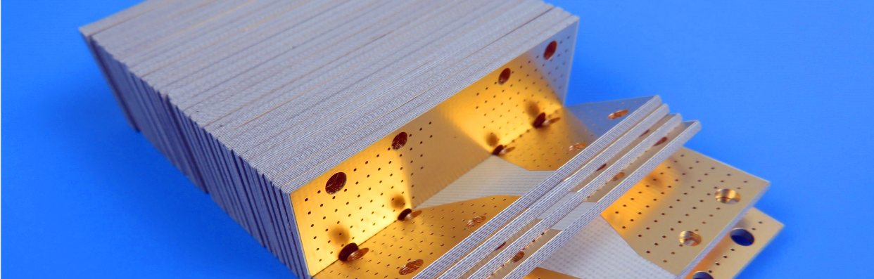
Rogers TC600 Microwave PCB with 15mil 20mil 30mil 50mil 60mil TC600 Immersion Silver PCB for Power Amplifiers
Printed Circuit Boards are custom-made products; the images and specifications provided are for reference only.
Introduction
Rogers (Arlon) TC600 PCB stands as a cutting - edge composite material, expertly crafted with woven fiberglass reinforcement and ceramic filling in a PTFE matrix. Engineered to be a game - changer, it offers unparalleled heat - transfer capabilities, boasting industry - leading thermal conductivity. TC600 PCB not only allows for superior power management but also eliminates overheating issues, significantly enhancing the reliability of electronic devices.
One of its most notable features is the remarkable reduction in dielectric and insertion losses. This translates into higher gains and efficiencies for amplifiers and antennas, ensuring optimal performance in signal transmission. The material's stable dielectric constant across an extensive temperature range from - 40°C to 140°C (with a coefficient of - 75 ppm/°C) is a major advantage. Rogers TC600 laminate empowers power amplifier and antenna designers to maintain peak performance, preventing bandwidth losses that typically occur due to dielectric constant fluctuations with temperature changes.
Moreover, Rogers TC600 PCB's low Z - direction coefficient of thermal expansion (CTE) and enhanced mechanical strength make it a top choice in the 6.15 dielectric constant market. TC600 laminate combines exceptional thermal, electrical, and mechanical properties, setting a new standard for high - performance composite materials in a wide array of applications.
.jpg)
Features of Rogers TC600 PCB:
1. Very Low Loss Tangent (0.002 at 10 GHz) provides Higher Amplifier or Antenna Efficiency
2. Mechanically Robustness improves processing and reliability, replaces brittle laminates that cannot withstand processing, impact or High Gain forces
3. Low coefficient of thermal expansion on X,Y and Z axis (9, 9 and 35 ppm/°C) matches active components for low stress solder joints
4. High Peel Strength for Reliable narrow lines
.jpg)
Benefits of TC600 PCB:
1. Reduced Heat Generated through Transmission Line Loss
2. Heat Dissipation and Management
3. Replace Ceramic in Some Applications
4. Large Panel Sizes for Multiple Circuit Layout for lowered Processing Costs
Our PCB Capability (TC600)
PCB Capability (TC600) |
|
PCB Material: |
Ceramic Filled PTFE/Woven Fiberglass |
Designation: |
TC600 |
Dielectric constant: |
6.15 (10 GHz) |
Dissipation Factor |
0.002 (10 GHz) |
Layer count: |
Double Sided PCB, Multilayer PCB, Hybrid PCB |
Copper weight: |
1oz (35µm), 2oz (70µm) |
Dielectric thickness: |
10mil (0.254mm), 20mil (0.508mm), 30mil (0.762mm), 60mil (1.524mm) |
PCB size: |
≤400mm X 500mm |
Solder mask: |
Green, Black, Blue, Yellow, Red etc. |
Surface finish: |
Bare copper, HASL, Immersion gold, Immersion silver, Immersion tin, ENEPIG, OSP, Pure gold plated etc.. |
Typical Applications:
1. Digital Audio Broadcasting (DAB) Antennas (Satellite Radio)
2. GPS & Hand-held RFID Reader Antennas
3. Microwave Combiner and Power Divider Boards in Avionics Applications
4. Power Amplifiers, Filters and Couplers
5. Small Footprint Antennas
Appendix: Typical Values of TC600
| Property | Unit | Value | Test Method |
| 1. Electrical Properties | |||
| Dielectric Constant (may vary by thickness) | |||
| @1.8 MHz | - | 6.15 | Resonant Cavity |
| @10 GHz | - | 6.15 | IPC TM-650 2.5.5.5 |
| Dissipation Factor | |||
| @1.8 GHz | - | 0.0017 | Resonant Cavity |
| @10 GHz | - | 0.002 | IPC TM-650 2.5.5.5 |
| Temperature Coefficient of Dielectric | - | ||
| TCεr @ 10 GHz (-40-150°C) | ppm/ºC | -75 | IPC TM-650 2.5.5.5 |
| Volume Resistivity | |||
| C96/35/90 | MΩ-cm | 1.6x10⁹ | IPC TM-650 2.5.17.1 |
| E24/125 | MΩ-cm | 2.4x10⁸ | IPC TM-650 2.5.17.1 |
| Surface Resistivity | |||
| C96/35/90 | MΩ | 3.1x10⁹ | IPC TM-650 2.5.17.1 |
| E24/125 | MΩ | 9.0x10⁸ | IPC TM-650 2.5.17.1 |
| Electrical Strength | Volts/mil (kV/mm) | 850 (34) | IPC TM-650 2.5.6.2 |
| Dielectric Breakdown | kV | 62 | IPC TM-650 2.5.6 |
| Arc Resistance | sec | >240 | IPC TM-650 2.5.1 |
| 2. Thermal Properties | |||
| Decomposition Temperature (Td) | |||
| Initial | °C | 512 | IPC TM-650 2.4.24.6 |
| 5% | °C | 572 | IPC TM-650 2.4.24.6 |
| T260 | min | >60 | IPC TM-650 2.4.24.1 |
| T288 | min | >60 | IPC TM-650 2.4.24.1 |
| T300 | min | >60 | IPC TM-650 2.4.24.1 |
| Thermal Expansion, CTE (x,y) 50-150ºC | ppm/ºC | 9, 9 | IPC TM-650 2.4.41 |
| Thermal Expansion, CTE (z) 50-150ºC | ppm/ºC | 35 | IPC TM-650 2.4.24 |
| % z-axis Expansion (50-260ºC) | % | 1.5 | IPC TM-650 2.4.24 |
| 3. Mechanical Properties | |||
| Peel Strength to Copper (1 oz/35 micron) | |||
| After Thermal Stress | lb/in (N/mm) | 10 (1.8) | IPC TM-650 2.4.8 |
| At Elevated Temperatures (150ºC) | lb/in (N/mm) | 10 (1.8) | IPC TM-650 2.4.8.2 |
| After Process Solutions | lb/in (N/mm) | 9 (1.6) | IPC TM-650 2.4.8 |
| Young’s Modulus | kpsi (MPa) | 280 (1930) | IPC TM-650 2.4.18.3 |
| Flexural Strength (Machine/Cross) | kpsi (MPa) | 9.60/9.30 (66/64) | IPC TM-650 2.4.4 |
| Tensile Strength (Machine/Cross) | kpsi (MPa) | 5.0/4.30 (34/30) | IPC TM-650 2.4.18.3 |
| Compressive Modulus | kpsi (MPa) | ASTM D-3410 | |
| Poisson’s Ratio | - | ASTM D-3039 | |
| 4. Physical Properties | |||
| Water Absorption | % | 0.02 | IPC TM-650 2.6.2.1 |
| Density, ambient 23ºC | g/cm3 | 2.9 | ASTM D792 Method A |
| Thermal Conductivity (z-axis) | W/mK | 1.1 | ASTM E1461 |
| Thermal Conductivity (x, y) | W/mK | 1.4 | ASTM E1461 |
| Specific Heat | J/gK | 0.94 | ASTM E1461 |
| Flammability | class | V0 | UL-94 |
| NASA Outgassing, 125ºC, ≤10-6 torr | |||
| Total Mass Loss | % | 0.02 | NASA SP-R-0022A |
| Collected Volatiles | % | 0 | NASA SP-R-0022A |
| Water Vapor Recovered | % | 0 | NASA SP-R-0022A |