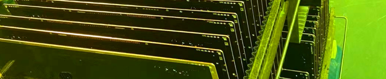
Taconic TLX-8 PCB Raw Materials Introduction Today, we’re going to talk about a type of high volume fiberglass reinforced microwave copper clad laminate ----TLX-8 laminate, which offers reliability in a wide range of RF applications. Taconic TLX-8 high frequency circuit materials are ideal for use in radar systems, mobile communications, microwave test equipment and microwave transmission devices. TLX-8 Typical Properties Let's dive into the technical specifications and explore what makes this product special. One of the key features of the TLX-8 laminate is its dielectric constant (DK) at 10 GHz, which is measured to be 2.55. This value indicates the material's ability to store electrical energy in an electromagnetic field. With a DK of 2.55,Taconic TLX-8 laminate offers excellent performance in terms of signal transmission and impedance control. Next, let's take a look at the dissipation factor (Df) at different frequencies. At 1.9 GHz, Taconic TLX-8 has a Df of 0.0012, and at 10 GHz, it measures at 0.0017. The low Df values indicate minimal loss of signal energy during transmission, ensuring high signal integrity and low signal distortion. Its dielectric breakdown is more than 45 kilo-voltages and moisture absorption rate features impressively low at 0.02% Moving on to mechanical properties, Taconic TLX-8 laminate demonstrates impressive strength. It has a flexural strength of 28,900 psi (or 20,600 N/mm2) in the machine direction (MD) and 20,600 psi (or 28,900 N/mm2) in the cross direction (CD). Additionally, the tensile strength is measured at 35,600 psi (or 27,500 N/mm2) in the MD and CD orientations. This robustness ensures the TLX-8 can withstand various mechanical stresses and maintain its structural integrity. According to ASTM D 902, the material exhibits an elongation at break of 3.94% in the machine direction (MD), indicating its ability to stretch before breaking. In the cross direction (CD), as per ASTM D 902, the material demonstrates a similar elongation at break of 3.92%, showcasing its flexibility and resistance to tearing. The material's Young's Modulus is measured to be 980 kpsi (or 1,630 N/mm2) in the machine direction (MD) based on ASTM D 902, indicating its stiffness and resistance to deformation under tension. Similarly, in the cross direction (CD) following ASTM D 902, the Young's Modulus is determined to be 1,200 kpsi (or 1,200 N/mm2), highlighting its ability to withstand stretching forces. As per ASTM D 3039, the Young's Modulus in the machine direction (MD) is reported to be 1,630 kpsi (or 1,630 N/mm2), indicating the material's high resistance to deformation in that direction. The material's Poisson's Ratio, determined according to ASTM D 3039, is found to be 0.135 (or 0.135 N/mm), indicating a slight tendency to contract in the transverse direction when stretched longitudinally. Then let’s see the peel strength. The data sheet gives us 4 situations: 1oz and half ounces ED copper, 1oz reverse treated copper and 1oz rolled copper. Their peel strengths are very similar to each other. All of them are more than 10 Ibs./linear inch. The peel strength of the material, evaluated as per IPC-650 2.4.8 Sec.5.2.2 (Thermal Stress), reveals a value of 15 lbs./linear inch (or 17 N/mm) for 1 oz. electrodeposited (ed) material, showcasing its adhesive strength and resistance to delamination under thermal stress conditions. Similarly, for 1 oz. rolled through hole (RTF) material, the peel strength is determined to be 17 lbs./linear inch (or 17 N/mm), further highlighting its strong bonding properties under thermal stress conditions. The 1/2 oz. electrodeposited (ed) material demonstrates a peel strength of 14 lbs./linear inch (or 11 N/mm) according to IPC-650 2.4.8.3 (Elevated Temp.), indicating its ability to withstand delamination at elevated temperatures. Under thermal stress conditions, the peel strength of the 1/2 oz. electrodeposited (ed) material is measured to be 11 lbs./linear inch (or 11 N/mm) as per IPC-650 2.4.8 Sec.5.2.2, suggesting its resistance to delamination even in challenging thermal environments. The peel strength of 1 oz. rolled material, evaluated according to IPC-650 2.4.8 Sec.5.2.2 (Thermal Stress), is determined to be 13 lbs./linear inch (or 13 N/mm), indicating its ability to maintain adhesion under thermal stress conditions. In terms of dimensional stability, the TLX-8 exhibits minimal changes even under different conditions. After baking, the dimensional stability is 0.06 mils/in. (or 0.09 mm/M) in the MD direction and 0.08 mils/in. (or 0.1 mm/M) in the CD direction. Similarly, under thermal stress, the TLX-8 maintains its shape with a dimensional stability of 0.09 mils/in. (or 0.09 mm/M) in the MD and 0.1 mils/in. (or 0.1 mm/M) in the CD. These properties of higher peel strength and lower value in dimensional expansion help the PCB undergo extreme environment at sea or wide range of temperature variation in the flight. Additionally, the TLX-8 has exceptional electrical properties. It exhibits high surface resistivity, measuring at 6.605 x 10^8 Mohm under elevated temperature conditions and 3.550 x 10^6 Mohm under humidity conditions. Similarly, the volume resistivity is measured at 1.110 x 10^10 Mohm/cm under elevated temperature conditions and 1.046 x 10^10 Mohm/cm under humidity conditions. Now let's talk about thermal properties. The TLX-8 offers thermal conductivity at 0.19 W/M*K, enabling heat dissipation in electronic applications. It also has a low coefficient of thermal expansion (CTE) of 21 ppm/°C in the X-axis and 23 ppm/°C in the Y-axis, indicating minimal dimensional changes with temperature fluctuations. However, in the Z-axis, the CTE is higher at 215 ppm/°C. The density (specific gravity) of the material, determined according to ASTM D 792, is reported to be 2.25 g/cm3, indicating its compact and solid nature. The material demonstrates a temperature at which 2% weight loss occurs (Td) of 535°C as per IPC-650 2.4.24.6 (TGA), indicating its thermal stability and ability to withstand high temperatures. Similarly, the temperature at which 5% weight loss occurs (Td) is determined to be 553°C according to IPC-650 2.4.24.6 (TGA), further highlightingits resistance to thermal degradation and its ability to maintain its structural integrity at elevated temperatures. To ensure safety, the TLX-8 has a flammability rating of UL-94 V-0, indicating its high resistance to combustion. Property Test Method Unit TLX-8 Value Unit Value DK @10 GHz IPC-650 2.5.5.3 2.55 2.55 Df @1.9 GHz IPC-650 2.5.5.5.1 0.0012 0.0012 Df @10 GHz IPC-650 2.5.5.5.1 0.0017 0.0017 Dielectric Breakdown IPC-650 2.5.6 kV >45 kV >45 Moisture Absorption IPC-650 2.6.2.1 % 0.02 % 0.02 Flexural Strength(MD) ASTM D 709 psi 28,900 N/mm2 Flexural Strength(CD) ASTM D 709 psi 20,600 N/mm2 Tensile Strength(MD) ASTM D 902 psi 35,600 N/mm2 Tensile Strength(CD) ASTM D 902 psi 27,500 N/mm2 Elongation at Break(MD) ASTM D 902 % 3.94 % 3.94 Elongation at Break(CD) ASTM D 902 % 3.92 % 3.92 Young's Modulus(MD) ASTM D 902 kpsi 980 N/mm2 Young's Modulus(CD) ASTM D 902 kpsi 1,200 N/mm2 Young's Modulus(MD) ASTM D 3039 kpsi 1,630 N/mm2 Poisson's Ratio ASTM D 3039 0.135 N/mm Peel Stength(1 oz.ed) IPC-650 2.4.8 Sec.5.2.2(Thermal Stress.) Ibs./linear inch 15 N/mm Peel Stength(1 oz.RTF) IPC-650 2.4.8 Sec.5.2.2(Thermal Stress.) Ibs./linear inch 17 N/mm Peel Stength(½ oz.ed) IPC-650 2.4.8.3(Elevated Temp.) Ibs./linear inch 14 N/mm TLX family There’s TLX-0, TLX-9, TLX-8, TLX-7 and TLX-6 in the TLX family. TLX materials are PTFE-based fiberglass laminates. They are versatile due to its 2.45 - 2.65 DK range and available thicknesses and copper cladding. It is suitable for low layer count microwave designs. TLX is noteworthy because it is available as a very thin laminate for coupler type applications.TLX-9 has the thinnest thickness of 2mil and TLX-0 has the lowest DK of 2.45 TLX is a workhorse in the world of RF microwave substrates because fiberglass provides mechanical reinforcement wherever they encounter harsh environments. A Piece of TLX-8 Substrate Now on the screen is a TLX-8 substrate. Taconic TLX-8 PCB materials also can be found in radar systems, mobile communications, antennas, mixer, filters,combiners and splitters etc. TLX-8’s Outgassing Properties Taconic TLX-8 high frequency laminate has tightly controlled DK, there’s only ± 2% variation from -55 to 125 °C. It has a long space heritage and is able to experience severe environments such as radiation resistance in space. From this outgassing test report, we can see total mass loss (TML) of TLX-8 laminate is 0.03%. Collected volatile condensable materials (CVCM) is zero and the amount of water vapor regained (WVR) is 0.01%. These values are very low, which get much higher result than the normal required value. Property Test Method Units Value Outgassing (%TML) ASTM E 595 24 H 257 °F @ ≤ 5 x 10⁻⁵ Torr 0.03 Outgassing (%CVCM) ASTM E 595 24 H 257 °F @ ≤ 5 x 10⁻⁵ Torr 0.00 Outgassing (%WVR) ASTM E 595 24 H 257 °F @ ≤ 5 x 10⁻⁵ Torr 0.01 Conclusion In conclusion, Taconic TLX-8 PCB substrate is an outstanding material that offers a combination of excellent electrical, mechanical, and thermal properties. Taconic TLX-8 PCB material provides stable performance in various applications, making it an ideal choice for high-frequency PCB designs, where signal integrity and reliability are paramount. That wraps up our discussion on the TLX-8 laminate. Thank you for joining us today, and if you have any further questions, feel free to ask our experts. I’ll see you next time.


 Home
Home