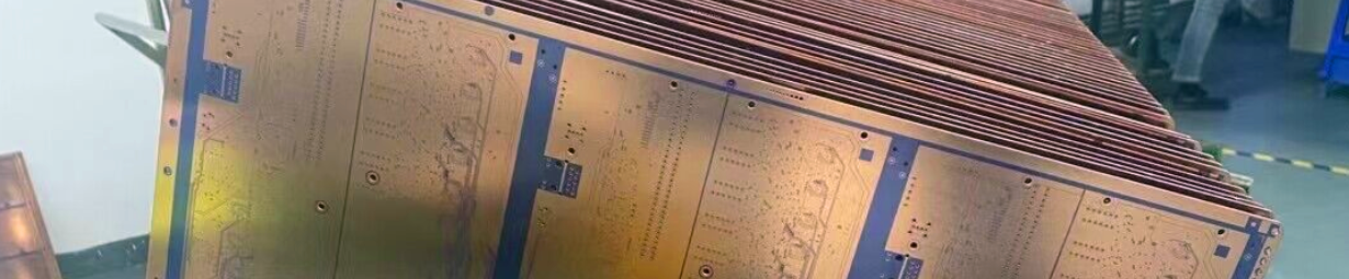
Rogers RT/duroid 5880LZ High Frequency PCB Material Introduction Today, let’s talk about a type of lightweight high frequency circuit board Material: Rogers RT/duroid 5880LZ . Rogers RT/duroid 5880LZ laminates are filled PTFE composites designed for exacting strip-line and micro-strip circuit applications. They contain a unique filler that results in a low density, lightweight material for high performance and weight sensitive applications. RT/duroid 5880LZ Typical Properties Rogers RT/duroid 5880LZ is an impressive PCB material that offers a range of outstanding properties. Let's take a closer look at some of its key features. First and foremost, let's discuss the dielectric constant of RT/duroid 5880LZ laminate. It has a process value of 2.00 ± 0.04 at 10 GHz and 23°C, ensuring reliable signal transmission in the Z direction, as per IPC-TM-650, 2.5.5.5. The design dielectric constant is also 2.00 in the Z direction, covering a frequency range from 8 GHz to 40 GHz, as determined by the differential phase length method. The dissipation factor, also known as tan delta, is impressively low, with a typical value of 0.0021 and a maximum of 0.0027 at 10 GHz and 23°C. This indicates minimal signal loss and excellent performance. Rogers RT/duroid 5880LZ copper clad laminate exhibits a thermal coefficient of dielectric constant of +20 ppm/°C in the Z direction, from -50°C to 150°C at 10 GHz, as specified by IPC-TM-650, 2.5.5.5. This ensures stable performance across a wide temperature range. In terms of electrical properties, RT/duroid 5880LZ demonstrates a volume resistivity of 1.74 x 10^7 Mohm?cm and a surface resistivity of 2.08 x 10^6 Mohm, as tested under C-96/35/90 conditions, according to IPC-TM-650, 2.5.17.1. The electrical strength of RT/duroid 5880LZ is measured at 40 KV, ensuring its durability and reliability in demanding applications, as per D48/50 specifications in IPC-TM-650, 2.5.6. When it comes to dimensional stability, RT/duroid 5880LZ showcases a remarkable performance with a dimensional change of -0.38% in the X and Y directions, ensuring consistent and reliable performance, as tested under IPC-TM-650, 2.4.39A. The moisture absorption of RT/duroid 5880LZ is 0.31% after 24 hours at 23°C, indicating its ability to resist moisture penetration, as specified by IPC-TM-650, 2.6.2.1. RT/duroid 5880LZ exhibits a thermal conductivity of 0.33 W/m/°K in the Z direction at 80°C as tested by ASTM C518. The coefficient of thermal expansion of RT/duroid 5880LZ is 54 ppm/°C in the X direction, 47 ppm/°C in the Y direction, and 40 ppm/°C in the Z direction, from 0°C to 150°C, ensuring dimensional stability under varying temperature conditions, according to IPC-TM-650, 2.4.41. RT/duroid 5880LZ has undergone rigorous testing for outgassing, meeting the requirements of ASTM E-595, with low values for Total Mass Loss (TML), Collected Volatile Condensable Materials (CVCM), and Water Vapor Regain (WVR), all at 0.01%. The material has a density of 1.4 gm/cm^3, providing a lightweight yet robust solution for high-frequency applications, as determined by ASTM D792. The copper peel strength of RT/duroid 5880LZ is greater than 4.0 pli, ensuring excellent adhesion and reliability in copper bonding processes, as tested under IPC-TM-650, 2.4.8. RT/duroid 5880LZ has achieved a V-O rating for flammability according to UL 94, ensuring its resistance to ignition and flame propagation. Lastly, RT/duroid 5880LZ is compatible with lead-free processes, offering a reliable and environmentally friendly solution for your electronic applications. Property RT/duroid 5880LZ Direction Units Condition Test Method Dielectric Constant er,Process 2.00 ± 0.04 Z 10 GHz/23°C IPC-TM-650, 2.5.5.5 Dielectric Constant er,Design 2.00 Z 8 GHz - 40 GHz Differential Phase Length Method Dissipation Factor, tan Typ: 0.0021 Max: 0.0027 Z 10GHz/23°C IPC-TM-650, 2.5.5.5 Thermal Coefficient of Dielectric Constant, er +20 Z ppm/°C -50°C to 150°C 10GHz IPC-TM-650, 2.5.5.5 Volume Resistivity 1.74 X 10^7 Mohm•cm C-96/35/90 IPC-TM-650, 2.5.17.1 Surface Resistivity 2.08 X 10^6 Mohm C-96/35/90 IPC-TM-650, 2.5.17.1 Electrical Strength 40 KV D48/50 IPC-TM-650, 2.5.6 Dimensional Stability -0.38 X,Y % IPC-TM-650, 2.4.39A Moisture Absorption 0.31 % 24 hours/23°C IPC-TM-650, 2.6.2.1 Thermal Conductivity 0.33 Z W/m/°K 80°C ASTM C518 Coefficient of Thermal Expansion 54,47,40 X,Y,Z ppm/°C 0 to 150°C IPC-TM-650, 2.4.41 Outgassing TML 0.01 % ASTM E-595 CVCM 0.01 WVR 0.01 Density 1.4 gm/cm^3 ASTM D792 Copper Peel >4.0 pli IPC-TM-650, 2.4.8 Flammability V-O UL 94 Lead-Free Process Compatible YES A Piece of RT/duroid 5880LZ Laminate Now what we are seeing on the screen is RT/duroid 5880LZ Laminate . Typical Applications (RT/duroid 5880LZ) In our lives, we can find their typical applications in the area of airborne antenna system, lightweight feed networks, military radar systems ,missile guidance systems,point-to-point digital radio antennas etc. Conclusion Rogers RT/duroid 5880LZ high frequency circuit material has Z-axis coefficient of thermal expansion (CTE) at 40 ppm/°C. This is a low value that ensure its reliable plated through holes.Rogers RT/duroid 5880LZ is engineered with a proprietary filler system, delivering an exceptionally low‑density and lightweight circuit material ideal for high‑performance applications where weight reduction is critical. RT/duroid 5880LZ advanced laminate combines superior electrical stability, low loss, and consistent dielectric properties across a wide frequency range, making it the preferred choice for antenna, lightweight feed networks and portable communication systems. With its optimized balance of mechanical integrity and RF performance, RT/duroid 5880LZ enables designers to achieve lighter, more efficient, and reliable high‑frequency designs without compromising signal integrity. OK. This concludes today’s episode. Thank you for reading. See you next time.
.jpg)


 Home
Home