
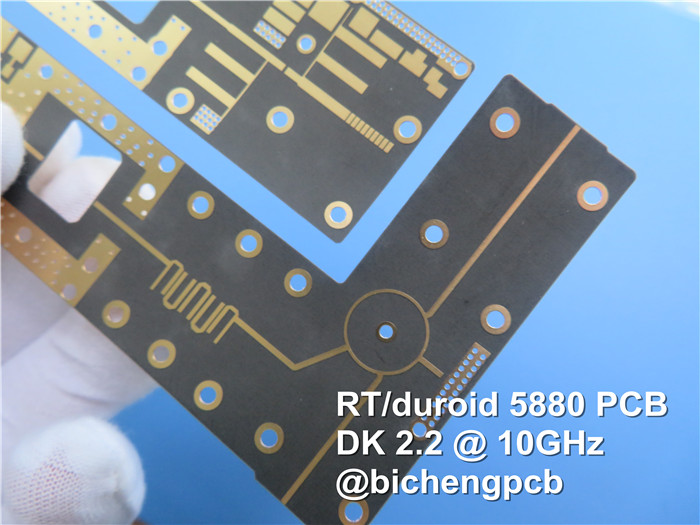
RT/duroid 5880 High Frequency PCB Material Introduction Greetings everyone, Today, we would like to introduce you to a high-frequency PCB that utilizes the reliable RT/duroid 5880 laminates. Rogers RT/duroid 5880 PCBs are specifically designed for precise stripline and microstrip circuit applications. These laminates consist of PTFE composites reinforced with glass microfibers, offering exceptional performance in high-frequency scenarios. One of the notable features of RT/duroid 5880 laminates is their low dielectric constant (Dk) and low dielectric loss, which makes them highly suitable for high-frequency and broadband applications. Their low Dk ensures minimal signal loss and excellent signal integrity. The presence of randomly oriented microfibers within the laminate contributes to exceptional dielectric constant uniformity. This means that the dielectric constant remains consistent from panel to panel and remains stable over a wide frequency range. Such uniformity is crucial for maintaining consistent electrical performance across the entire PCB. Additionally, the low dissipation factor of RT/duroid 5880 laminates extends their usability to frequencies in the Ku-band and beyond. This property allows these laminates to effectively handle high-frequency signals without significant energy loss or degradation. Data sheet Rogers RT/duroid 5880 Data Sheet Summary: Dielectric Constant: Process: 2.20 (2.20±0.02 spec.) at 1 MHz, C24/23/50 test method Design: 2.2 at 8 GHz to 40 GHz, determined using the Differential Phase Length Method Dissipation Factor (tanδ): Process: 0.0004 at 1 MHz, C24/23/50 test method Process: 0.0009 at 10 GHz, IPC-TM 2.5.5.5 test method Thermal Coefficient of ε: -125 ppm/°C in the temperature range of -50°C to 150°C, IPC-TM-650 2.5.5.5 test method Volume Resistivity: 2 x 10^7 Mohm cm, measured using ASTM D 257 Surface Resistivity: 3 x 10^7 Mohm, measured using ASTM D 257 Specific Heat: 0.96 j/g/°C (0.23 cal/g/°C), calculated value Tensile Modulus: Test at 23°C: 1070 MPa (156 kpsi) in the X direction, 860 MPa (125 kpsi) in the Y direction Test at 100°C: 450 MPa (65 kpsi) in the X direction, 380 MPa (55 kpsi) in the Y direction Ultimate Stress: Test at 23°C: 29 MPa (4.2 kpsi) in the X direction, 27 MPa (3.9 kpsi) in the Y direction Test at 100°C: 20 MPa (2.9 kpsi) in the X direction, 18 MPa (2.6 kpsi) in the Y direction Ultimate Strain: Test at 23°C: 6% in the X direction, 4.9% in the Y direction Test at 100°C: 7.2% in the X direction, 5.8% in the Y direction Compressive Modulus: Test at 23°C: 710 MPa (103 kpsi) in the X and Y directions, 940 MPa (136 kpsi) in the Z direction Test at 100°C: 500 MPa (73 kpsi) in the X and Y directions, 670 MPa (97 kpsi) in the Z direction Moisture Absorption: 0.02% for 0.62" (1.6mm) thickness, ASTM D 570 test method Thermal Conductivity: 0.2 W/m/°C at 80°C, ASTM C 518 test method Coefficient of Thermal Expansion: X direction: 31 ppm/°C in the range of 0-100°C Y direction: 48 ppm/°C in the range of 0-100°C Z direction: 237 ppm/°C in the range of 0-100°C Td (Thermal Decomposition Temperature): 500°C, determined using TGA (Thermogravimetric Analysis), ASTM D 3850 test method Density: 2.2 gm/cm3, measured using ASTM D 792 Copper Peel: 31.2 pli (5.5 N/mm) for 1oz (35mm) EDC foil after solder float, IPC-TM-650 2.4.8 test method Flammability: V-0 rating, UL 94 test method Lead-free Process Compatible: Yes RT/duroid 5880 Typical Value Property RT/duroid 5880 Direction Units Condition Test Method Dielectric Constant,εProcess 2.20 Z N/A C24/23/50 1 MHz IPC-TM-650 2.5.5.3 Dielectric Constant,εDesign 2.2 Z N/A 8GHz to 40 GHz Differential Phase Length Method Dissipation Factor,tanδ 0.0004 Z N/A C24/23/50 1 MHz IPC-TM-650 2.5.5.3 Thermal Coefficient of ε -125 Z ppm/℃ -50℃to 150℃ IPC-TM-650 2.5.5.5 Volume Resistivity 2 x 10⁷ Z Mohm cm C/96/35/90 ASTM D 257 Surface Resistivity 3 x 10⁷ Z Mohm C/96/35/90 ASTM D 257 Specific Heat 0.96(0.23) N/A j/g/k N/A Calculated Tensile Modulus Test at 23℃ Test at 100℃ N/A MPa(kpsi) A ASTM D 638 1070(156) 450(65) X 860(125) 380(55) Y Ultimate Stress 29(4.2) 20(2.9) X 27(3.9) 18(2.6) Y Ultimate Strain 6 7.2 X % 4.9 5.8 Y Compressive Modulus 710(103) 500(73) X MPa(kpsi) A ASTM D 695 710(103) 500(73) Y 940(136) 670(97) Z Ultimate Stress 27(3.9) 22(3.2) X 29(5.3) 21(3.1) Y 52(7.5) 43(6.3) Z Ultimate Strain 8.5 8.4 X % 7.7 7.8 Y 12.5 17.6 Z Moisture Absorption 0.02 N/A % 0.62"(1.6mm) D48/50 ASTM D 570 Thermal Conductivity 0.2 Z W/m/k 80℃ ASTM C 518 Coefficient of Thermal Expansion 31 X ppm/℃ 0-100℃ IPC-TM-650 2.4.41 Td 500 N/A ℃ TGA N/A ASTM D 3850 Density 2.2 N/A gm/cm3 N/A ASTM D 792 Copper Peel 31.2(5.5) N/A Pli(N/mm) 1oz(35mm)EDC foil IPC-TM-650 2.4.8 Flammability V-0 N/A N/A N/A UL 94 Lead-free Process Compatible Yes N/A N/A N/A N/A PCB Capability (RT/duroid 5880) Our manufacturing capability for RT/duroid 5880 PCB includes various options to accommodate different design requirements. We can produce single-sided, double-sided, multi-layer, and hybrid PCBs using the versatile RT/duroid 5880 laminates. When it comes to copper weight, we offer flexibility with options such as 1oz (35µm) and 2oz (70µm). This allows us to meet specific conductivity needs for different applications. Laminate thickness is another aspect we consider. With RT/duroid 5880, we provide choices ranging from 5mil (0.127mm) to 62mil (1.575mm). This versatility allows us to accommodate varying mechanical and electrical requirements for our customers' PCB designs. In terms of PCB size, we can manufacture boards up to ≤400mm X 500mm using RT/duroid 5880 laminates. This ensures that we can handle a wide range of board dimensions while maintaining the material's performance characteristics. To cater to different preferences and industry requirements, we offer a selection of solder mask colors including green, black, blue, yellow, red, and more. This allows our customers to customize the appearance of their PCBs based on their desired aesthetics or specific industry standards. When it comes to surface finish, we provide multiple options such as bare copper, HASL, ENIG, immersion silver, immersion tin, ENEPIG, pure gold, OSP, and more. These options address various needs for solderability, corrosion resistance, and overall PCB performance. PCB Capability (RT/duroid 5880) PCB Material: Glass microfiber reinforced PTFE composites Designation: RT/duroid 5880 Dielectric constant: 2.20±0.02 Layer count: Single Sied, Double Sided, Multi-layer, Hybrid PCB Copper weight: 1oz (35µm), 2oz (70µm) Laminate thickness: 5mil (0.127mm), 10mil (0.254mm), 20mil(0.508mm), 31mil (0.787mm), 62mil(1.575mm) PCB size: ≤400mm X 500mm Solder mask: Green, Black, Blue, Yellow, Red etc. Surface finish: Bare copper, HASL, ENIG, Immersion silver, Immersion tin, ENEPIG, Pure gold, OSP etc.. Applications Rogers RT/duroid 5880 PCBs are widely used in various applications, including: Commercial Airline Broadband Antennas, Microstrip and Stripline Circuits, Millimeter Wave Applications, Military Radar Systems, Missile Guidance Systems, Point to Point Digital Radio Antennas etc.
2.20±0.02 spec.
C24/23/50
10 GHz IPC-TM 2.5.5.5
0.0009
C24/23/50
10 GHz IPC-TM 2.5.5.5
(cal/g/c)
48
237
Y
Z
after solder float


 Home
Home