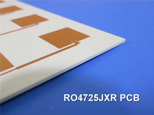
RO4725JXR High Frequency PCB Material Introduction Hello and welcome back to our channel. I am Jane, the regional sales manager for BichengPCB. Today, we're going to talk about an exciting new development in the world of antenna design: RO4725JXR antenna grade PCB. In the world of antenna design, finding the right material for the job can be a daunting task. Thankfully, RO4725JXR antenna grade laminates provide a reliable and efficient alternative to conventional PTFE-based laminates that have been used in antenna design for many years. With its exceptional mechanical and electrical properties, antenna designers can achieve substantial gain values while minimizing signal loss. The materials are compatible with conventional epoxy and high temperature lead-free solder processing, do not require special treatment for plated through hole preparation and lamination can be achieved using the RO4400 bondply series at 175°C. Here are more details on the data sheet. RO4725JXR Typical Properties RO4725JXR has a process dielectric constant of 2.55 ± 0.05 in the Z direction at 10 GHz and 23°C, as measured by the IPC-TM-650, 2.5.5.5 test method. Its design dielectric constant is 2.64 in the Z direction at 1.7 GHz to 5 GHz, as measured by the differential phase length method. It has a dissipation factor of 0.0026 in the Z direction at 10 GHz and 23°C, as measured by the IPC-TM-650, 2.5.5.5 test method. At 2.5 GHz, its dissipation factor is 0.0022. It also has a thermal coefficient of dielectric constant of +34 ppm/°C in the Z direction between -50°C to 150°C, as measured by the IPC-TM-650, 2.5.5.5 test method. RO4725JXR has a volume resistivity of 2.16 X 10^8 M??cm and a surface resistivity of 4.8 X 10^7 M? at 0.030", both measured under COND A using the IPC-TM-650, 2.5.17.1 test method. The laminate has a very low PIM value of -166 dBc at 50 ohm on 0.060" thick material, with a power level of 43 dBm at 1900MHz. Its electrical strength is 630 V/mil at 0.030", as measured by the IPC-TM-650, 2.5.6.2 test method. Its flexural strength is 121 MPa in the MD direction and 92 MPa in the CMD direction, as measured by the ASTM D790 test method at room temperature. RO4725JXR has a dimensional stability of less than 0.4 mm/m in the X and Y directions after etch, with an E2/150°C condition, as measured by the IPC-TM-650, 2.4.39A test method. Its coefficient of thermal expansion is 13.9 ppm/°C in the X direction, 19.0 ppm/°C in the Y direction, and 25.6 ppm/°C in the Z direction between -55°C to 288°C, as measured by the IPC-TM-650, 2.1.24 test method. The thermal conductivity of RO4725JXR is 0.38 W/mK° at 50°C, as measured by the ASTM D5470 test method. Its moisture absorption is 0.24% at 48 hours 50oC, as measured by the IPC-TM-650 2.6.2.1 and ASTM D570 test methods. The material has a Tg value greater than 280°C, as measured by the IPC-TM-650 2.4.24 test method, and a Td value of 439°C, as measured by the ASTM D3850 test method. Its density is 1.27 gm/cm3, as measured by the ASTM D792 test method. RO4725JXR has a copper peel strength of 8.5 pli for 1 oz LoPro ED copper, as measured by the IPC-TM-650 2.4.8 test method. It is also lead-free process compatible. Property Typical Value Direction Units Condition Test Method Dielectric Constant, εr Process 2.55 ± 0.05 Z 10 GHz/23°C IPC-TM-650, 2.5.5.5 Dielectric Constant, εr Design 2.64 Z 1.7 GHz - 5 Differential Phase Length Method Dissipation Factor 0.0026 Z 10 GHz/23°C IPC-TM-650, 2.5.5.5 0.0022 2.5GHz Thermal Coefficient of εr +34 Z ppm/°C -50°C to 150°C IPC-TM-650, 2.5.5.5 Volume Resistivity (0.030") 2.16 X 10^8 MΩ•cm COND A IPC-TM-650, 2.5.17.1 Surface Resistivity (0.030") 4.8 X 10^7 MΩ COND A IPC-TM-650, 2.5.17.1 PIM -166 dBc 50 ohm 43dBm Electrical Strength (0.030”) 630 Z V/mil IPC-TM-650, 2.5.6.2 Flexural Strength MD 121 (17.5) MPa RT ASTM D790 CMD 92 (13.3) Dimensional Stability <0.4 X,Y mm/m after etch IPC-TM-650, 2.4.39A Coefficient of Thermal 13.9 X ppm/°C -55 TO 288°C IPC-TM-650, 2.1.24 19.0 Y 25.6 Z Thermal Conductivity 0.38 Z W/mK° 50°C ASTM D5470 Moisture Absorption 0.24% % 48/50 IPC-TM-650 2.6.2.1 ASTM D570 Tg >280 °C IPC-TM-650 2.4.24 Td 439 °C ASTM D3850 Density 1.27 gm/cm3 ASTM D792 Copper Peel Strength 8.5 pli 1 oz LoPro EDC IPC-TM-650 2.4.8 Lead-Free Process Compatible YES Our PCB Capability (RO4725JXR) A wide range of options is offered by our PCB capability to meet the diverse needs of our customers, including single-sided PCBs, double-sided PCBs, multi-layer PCBs, and hybrid PCBs that combine different technologies. Different requirements can be accommodated through a variety of dielectric thicknesses, such as 30.7mil (0.780mm) and 60.7mil (1.542mm). Customization of copper weight can also be provided according to your needs, with options for 1oz (35μm) and 2oz (70μm) copper weights. Rogers RO4725JXR PCBs are available in sizes up to 400mm X 500mm, making them suitable for a wide range of applications. We offer a variety of solder mask colors, including green, black, blue, red, yellow, and white etc. Additionally,RO4725JXR PCBs can be finished with a range of surface finishes, such as immersion gold, HASL, immersion silver, immersion tin, bare copper, OSP, ENEPIG, pure gold, and more. PCB Material: Hydrocarbon / Ceramic / Woven Glass Designation: RO4725JXR Dielectric constant: 2.55 (10 GHz) Dissipation factor 0.0026 (10 GHz) Layer count: Single Sided, Double Sided, Multi-layer PCB, Hybrid PCB Copper weight: 1oz (35µm), 2oz (70µm) Dielectric thickness 30.7mil (0.780mm), 60.7mil (1.542mm) PCB size: ≤400mm X 500mm Solder mask: Green, Black, Blue, Yellow, Red etc. Surface finish: Immersion gold, HASL, Immersion silver, Immersion tin, ENEPIG, OSP, Bare copper, Pure gold plated etc.. A Piece of RO4725JXR PCB Now on the screen is a type of PCB designed using Rogers RO4725JXR material, which is lead-free and can operate in temperatures ranging from -40℃ to +85℃. 1.542mm Rogers RO4725JXR PCB is double sided structure with a dielectric layer of 60.7mil with immersion gold (ENIG) on pads, no top or bottom silkscreen or solder mask. The typical application is cellular base station antennas. Conclusion When non-PTFE materials such as RO4725JXR are used for PCB antennas, their PIM performance consistently reaches levels even better than -164dBc. This special thermosetting resin and unique fillers material can achieve low PIM levels without sacrificing electrical and mechanical performance. Whether it is a base station antenna or other passive components (such as couplers and filters), PIM must be kept at the lowest level to ensure the highest quality of voice, data, and video communications in the system. Therefore, no matter how carefully the circuit is designed, the choice of PCB material largely determines the final achievable PIM.
GHz
0.060”
1900MHz
(kpsi)
+E2/150°C
Expansion


 Home
Home