
F4BM275 High Frequency PCB Materials Introduction Wangling F4BM275 is a premium high-frequency laminate developed as a core offering in the advanced F4BM series. F4BM275 features a precisely engineered composite of fiberglass reinforcement and PTFE resin, delivering exceptional electrical stability and minimal signal loss for demanding RF, microwave, and communication applications. F4BM275 PCB substrate ensures a consistent dielectric constant and ultra-low dissipation factor across a wide frequency range, providing reliable signal integrity in high-frequency circuits. With superior dimensional stability and robust thermal performance, F4BM275 laminate supports complex multilayer PCB designs and performs reliably in environments with temperature fluctuations. To meet diverse design requirements, F4BM275 laminate is available with multiple copper foil options, including RTF foil, enabling enhanced impedance control and reduced conductor loss in high-speed and high-frequency applications. Ideal for mission-critical uses, F4BM275 PCB raw material is widely applied in cellular infrastructure antennas, radar systems, phased-array designs, satellite communications, and 5G base stations — applications where uncompromising signal performance and manufacturing compatibility are essential. As a trusted domestic high-frequency material solution, F4BM275 offers a cost-effective, high-performance alternative that meets the stringent quality demands of advanced PCB designs. Features & Benefits -Low DK -Low loss -F4BM paired with RTF copper foil, excellent PIM performance -Diverse sizes, cost-effective -Radiation resistance, low outgassing -Commercialized, large-scale production, high cost-effectiveness Laminate Models and Data Sheet Here's a detailed description of each section of the data sheet: Product Model & Data Sheet: This section simply identifies the data sheet as the documentation for a range of product models. The models listed are F4BM217, F4BM220, F4BM233, F4BM245, F4BM255, F4BM265, F4BM275, F4BM294, and F4BM300. Product Features: This section provides an overview of the features of the products and introduces the technical parameters that will be described in the subsequent sections. Technical Parameters: Dielectric Constant (Typical): This parameter measures the relative permittivity of the material at a frequency of 10GHz. The data sheet lists the typical dielectric constant values for each product model. For example, F4BM217 has a dielectric constant of 2.17, while F4BM300 has a dielectric constant of 3.0. Dielectric Constant Tolerance: This parameter specifies the tolerance range for the dielectric constant values. The values listed indicate the allowable deviation from the typical dielectric constant values. The tolerance range is the same for all models. Loss Tangent (Typical): Loss tangent measures the dissipation of electromagnetic energy in the material. The data sheet provides loss tangent values at two different frequencies: 10GHz and 20GHz. Each model has specific loss tangent values associated with these frequencies. Dielectric Constant Temperature Coefficient: This parameter describes how the dielectric constant of the material changes with temperature. The data sheet provides temperature coefficient values in parts per million per degree Celsius (PPM/℃) over a temperature range of -55ºC to 150ºC. Each model has a different temperature coefficient value. Peel Strength: Peel strength refers to the adhesive strength between the material and a specified substrate. The data sheet lists peel strength values for two different conditions: 1 OZ F4BM and 1 OZ F4BME. The values indicate the minimum required peel strength for each model. Volume Resistivity: Volume resistivity measures the electrical resistance within the material. The data sheet provides minimum volume resistivity values under standard conditions. The unit of measurement is megaohm-centimeters (MΩ.cm), and all models have the same minimum value. Surface Resistivity: Surface resistivity measures the electrical resistance across the surface of the material. The data sheet provides minimum surface resistivity values under standard conditions. The unit of measurement is megaohms (MΩ), and all models have the same minimum value. Electrical Strength (Z direction): Electrical strength refers to the ability of the material to withstand electrical stress in the Z direction (perpendicular to the surface). The data sheet provides the minimum electrical strength values in kilovolts per millimeter (KV/mm) for each model. Breakdown Voltage (XY direction): Breakdown voltage is the voltage at which electrical breakdown occurs in the XY direction (parallel to the surface). The data sheet provides the minimum breakdown voltage values in kilovolts (KV) for each model. Coefficient of Thermal Expansion: This parameter describes how the material expands or contracts with changes in temperature. The data sheet provides coefficient of thermal expansion values in parts per million per degree Celsius (ppm/ºC) for both the XY direction and the Z direction. The values are given over a temperature range of -55ºC to 288ºC. Thermal Stress: Thermal stress is assessed by subjecting the material to specific temperature conditions. The data sheet indicates that the material does not experience delamination (separation of layers) when exposed to a temperature of 260℃ for 10 seconds, repeated three times. Water Absorption: Water absorption measures the amount of water the material can absorb under specific conditions. The data sheet lists the maximum water absorption values as a percentage of the material's weight. The measurements are taken at a temperature of 20±2℃ for 24 hours. Density: Density refers to the mass per unit volume of the material. The data sheet provides the density values at room temperature in grams per cubic centimeter (g/cm3) for each model. Long-Term Operating Temperature: This parameter specifies the recommended temperature range for long-term operation of the material. The data sheet indicates that all models can operate within a temperature range of -55 to +260℃. Thermal Conductivity: Thermal conductivity measures the material's ability to conduct heat. The data sheet provides the thermal conductivity values in the Z direction (perpendicular to the surface) in watts per meter-kelvin (W/(M.K)) for each model. PIM (Passive Intermodulation): Passive Intermodulation (PIM) is a measure of unwanted signal distortion. The data sheet states that PIM measurements are onlyapplicable to the F4BME model. Unfortunately, the specific values or units for PIM are not provided in the information you provided. Flammability: Flammability indicates the material's resistance to catching fire. The data sheet states that the material has a flammability rating of V-0 according to the UL-94 standard. The V-0 rating signifies the highest level of flame resistance. Material Composition: This section provides information about the composition of the material used in the products. It mentions that the material is composed of PTFE (polytetrafluoroethylene), fiberglass cloth, and copper foil. Product Technical Parameters Product Model & Data Sheet Product Features Test Conditions Unit F4BM217 F4BM220 F4BM233 F4BM245 Dielectric Constant (Typical) 10GHz / 2.17 2.2 2.33 2.45 Dielectric Constant Tolerance / / ±0.04 ±0.04 ±0.04 ±0.05 Loss Tangent (Typical) 10GHz / 0.001 0.001 0.0011 0.0012 20GHz / 0.0014 0.0014 0.0015 0.0017 Dielectric Constant Temperature Coefficient -55ºC~150ºC PPM/℃ -150 -142 -130 -120 Peel Strength 1 OZ F4BM N/mm >1.8 >1.8 >1.8 >1.8 1 OZ F4BME N/mm >1.6 >1.6 >1.6 >1.6 Volume Resistivity Standard Condition MΩ.cm ≥6×10^6 ≥6×10^6 ≥6×10^6 ≥6×10^6 Surface Resistivity Standard Condition MΩ ≥1×10^6 ≥1×10^6 ≥1×10^6 ≥1×10^6 Electrical Strength (Z direction) 5KW,500V/s KV/mm >23 >23 >23 >25 Breakdown Voltage (XY direction) 5KW,500V/s KV >30 >30 >32 >32 Coefficientof Thermal Expansion XY direction -55 º~288ºC ppm/ºC 25, 34 25, 34 22, 30 20, 25 Z direction -55 º~288ºC ppm/ºC 240 240 205 187 Thermal Stress 260℃, 10s,3 times No delamination No delamination No delamination No delamination Water Absorption 20±2℃, 24 hours % ≤0.08 ≤0.08 ≤0.08 ≤0.08 Density Room Temperature g/cm3 2.17 2.18 2.20 2.22 Long-Term Operating Temperature High-Low Temperature Chamber ℃ -55~+260 -55~+260 -55~+260 -55~+260 Thermal Conductivity Z direction W/(M.K) 0.24 0.24 0.28 0.30 PIM Only applicable to F4BME dBc ≤-159 ≤-159 ≤-159 ≤-159 Flammability / UL-94 V-0 V-0 V-0 V-0 Material Composition / / PTFE, Fiberglass Cloth Product Technical Parameters Product Model & Data Sheet Product Features Test Conditions Unit F4BM255 F4BM265 F4BM275 F4BM294 F4BM300 Dielectric Constant (Typical) 10GHz / 2.55 2.65 2.75 2.94 3.0 Dielectric Constant Tolerance / / ±0.05 ±0.05 ±0.05 ±0.06 ±0.06 Loss Tangent (Typical) 10GHz / 0.0013 0.0013 0.0015 0.0016 0.0017 20GHz / 0.0018 0.0019 0.0021 0.0023 0.0025 Dielectric Constant Temperature Coefficient -55ºC~150ºC PPM/℃ -110 -100 -92 -85 -80 Peel Strength 1 OZ F4BM N/mm >1.8 >1.8 >1.8 >1.8 >1.8 1 OZ F4BME N/mm >1.6 >1.6 >1.6 >1.6 >1.6 Volume Resistivity Standard Condition MΩ.cm ≥6×10^6 ≥6×10^6 ≥6×10^6 ≥6×10^6 ≥6×10^6 Surface Resistivity Standard Condition MΩ ≥1×10^6 ≥1×10^6 ≥1×10^6 ≥1×10^6 ≥1×10^6 Electrical Strength (Z direction) 5KW,500V/s KV/mm >25 >25 >28 >30 >30 Breakdown Voltage (XY direction) 5KW,500V/s KV >34 >34 >35 >36 >36 Coefficientof Thermal Expansion XY direction -55 º~288ºC ppm/ºC 16, 21 14, 17 14, 16 12, 15 12, 15 Z direction -55 º~288ºC ppm/ºC 173 142 112 98 95 Thermal Stress 260℃, 10s,3 times No delamination No delamination No delamination No delamination No delamination Water Absorption 20±2℃, 24 hours % ≤0.08 ≤0.08 ≤0.08 ≤0.08 ≤0.08 Density Room Temperature g/cm3 2.25 2.25 2.28 2.29 2.29 Long-Term Operating Temperature High-Low Temperature Chamber ℃ -55~+260 -55~+260 -55~+260 -55~+260 -55~+260 Thermal Conductivity Z direction W/(M.K) 0.33 0.36 0.38 0.41 0.42 PIM Only applicable to F4BME dBc ≤-159 ≤-159 ≤-159 ≤-159 ≤-159 Flammability / UL-94 V-0 V-0 V-0 V-0 V-0 Material Composition / / PTFE, Fiberglass Cloth A F4BM275 Substrate and Typical Applications Displayed on the screen is a F4BM275 substrate. F4BM275 is an advanced PTFE-based high-frequency laminate engineered to meet the rigorous demands of modern microwave, RF, and radar applications. It delivers exceptional electrical stability and low-loss performance, making it an ideal material for precision components such as phase shifters, power dividers, couplers, combiners, and complex feed networks in high-frequency circuit designs. This high-performance circuit material is widely used in advanced phased array antennas, satellite communication systems, and contemporary base station antennas, where consistent signal integrity and reliable operation in high-frequency environments are critical. With repeatable electrical properties and full compatibility with multilayer PCB processes, F4BM275 serves as a dependable substrate solution for high-frequency, high-reliability projects across telecommunications, aerospace, and defense industries. Whether for 5G infrastructure, radar systems, or aerospace communications, F4BM275 high frequency circuit material provides the electrical consistency, thermal stability, and manufacturing compatibility required for cutting-edge high-frequency PCB applications. Final - F4BM series aluminum-based/copper-based boards F4BM series PCB Materials can provide aluminum-based or copper-based materials, where one side of the dielectric layer is covered with copper foil, and the other side is covered with either aluminum-based material or copper-based , serving as shielding or heat dissipation purposes.
F4BM paired with ED copper foil, F4BME paired with reverse-treated (RTF) copper foil.
F4BM paired with ED copper foil, F4BME paired with reverse-treated (RTF) copper foil. 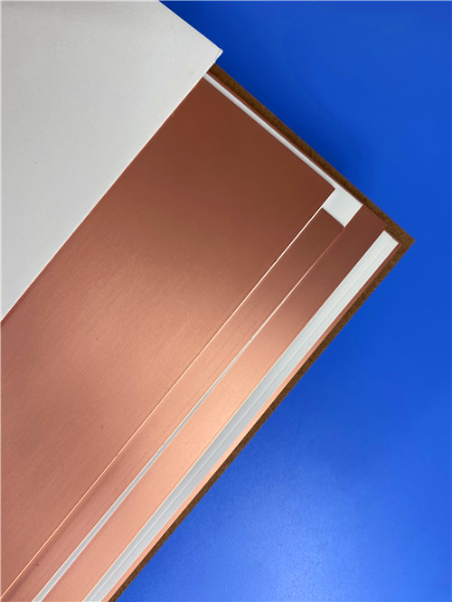


 Home
Home