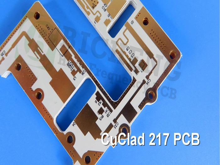
Rogers CuClad 217 High Frequency PCB Material Introduction Rogers CuClad® Laminates are high-performance woven fiberglass/PTFE composite materials designed as precision printed circuit board substrates. The exceptional performance of CuClad® Laminates stems from the precise control of the fiberglass-to-PTFE ratio, offering designers a selectable range from the lowest dielectric constant and loss tangent to more dimensionally stable, reinforced options. Compared to non-woven alternatives, the woven fiberglass reinforcement in CuClad® Laminates provides superior dimensional stability and dielectric uniformity. This controlled consistency allows CuClad® Laminates to cover a wider variety of dielectric constants, making them an ideal and reliable choice for critical RF components like filters, couplers, and low-noise amplifiers. A defining innovation of CuClad® Laminates is their unique cross-piled construction, where layers are oriented 90° to each other. This grants CuClad® Laminates true electrical and mechanical isotropy in the XY plane—a claim no other woven or non-woven PTFE-based laminate can make, proving critical for advanced applications such as phased array antennas. Rogers CuClad 217 laminate utilizes the lowest fiberglass-to-PTFE ratio in the series, achieving an exceptionally low dielectric constant (Er=2.17, 2.20) and the lowest dissipation factor available among woven fiberglass-reinforced PTFE laminates. These superior electrical properties directly translate to faster signal propagation speeds and maximized signal-to-noise ratios, making CuClad 217 laminate the ideal substrate for cutting-edge, high-speed digital and sensitive RF circuits where minimal signal loss is critical. Features & Benefits Cross Plied Woven Fiberglass, alternating plies are oriented 90o to each other High PTFE to Glass Ratio Better dielectric constant uniformity than comparable non-woven fiberglass reinforced laminates Electrical and Mechanical Isotropy in theX-Y Plane Extremely Low Loss Well Suited for Er Sensitive Circuits Data Sheet Typical Properties: CuClad Property Test Method Condition CuClad 217 CuClad 233 Cuclad 250 Dielectric Constant @10 GHz IPC TM-650 2.5.5.5 C23/50 2.17, 2.20 2.33 2.40 to 2.55 Dielectric Constant @1MHz IPC TM-650 2.5.5.3 C23/50 2.17, 2.20 2.33 2.40 to 2.60 Dissipation Factor @10 GHz IPC TM-650 2.5.5.5 C23/50 0.0009 0.0013 0.0017 Thermal Coefficient of Er (ppm/°C) IPC TM-650 2.5.5.5 Adapted -10°C to +140°C -160 -161 -153 Peel Strength (lbs.per inch) IPC TM-650 2.4.8 After Thermal Stress 14 14 14 Volume Resistivity (MΩ-cm) IPC TM-650 2.5.17.1 C96/35/90 2.3 x 10 8 8.0 x 10 8 8.0 x 10 9 Surface Resistivity (MΩ) IPC TM-650 2.5.17.1 C96/35/90 3.4 x 10 6 2.4 x 10 6 1.5 x 10 8 Arc Resistance (seconds) ASTM D-495 D48/50 >180 >180 >180 Tensile Modulus (kpsi) ASTM D-638 A, 23°C 275, 219 510, 414 725, 572 Tensile Strength (kpsi) ASTM D-882 A, 23°C 8.8, 6.6 10.3, 9.8 26.0, 20.5 Compressive Modulus (kpsi) ASTM D-695 A, 23°C 237 276 342 Flexural Modulus (kpsi) ASTM D-790 A, 23°C 357 371 456 Dielectric Breakdown (kv) ASTM D-149 D48/50 > 45 > 45 > 45 Specific Gravity (g/cm3) ASTM D-792 Method A A, 23°C 2.23 2.26 2.31 Water Absorption (%) MIL-S-13949H 3.7.7 IPC TM-650 2.6.2.2 E1/105 + D24/23 0.02 0.02 0.03 Coefficient of Thermal Expansion (ppm/°C) X Axis Y Axis Z Axis IPC TM-650 2.4.24 Mettler 3000 Thermomechanical Analyzer 0°C to 100°C 29 28 246 23 24 194 18 19 177 Thermal Conductivity ASTM E-1225 100°C 0.26 0.26 0.25 Outgassing Total Mass Loss (%) Collected Volatile Condensable Material (%) Water Vapor Regain (%) Visible Condensate (±) NASA SP-R-0022A Maximum 1.00% Maximum 0.10% 125°C, ≤ 10-6 torr 0.01 0.01 0.00 NO 0.01 0.01 0.00 NO 0.01 0.00 0.00 NO Flammability UL 94 Vertical Burn IPC TM-650 2.3.10 C48/23/50, E24/125 Meets requirements of UL94-V0 Meets requirements of UL94-V0 Meets requirements of UL94-V0 Our PCB Capability ( CuClad ) Rogers CuClad217 PCBs s are available with standard electrodeposited copper cladding of ½ oz, 1 oz, or 2 oz on both sides, with options for other copper weights and rolled copper foil upon request. Rogers CuClad217 laminates can also be supplied bonded to a heavy‑metal ground plane using aluminum, brass, or copper plates, which serve as an integral heat sink while providing enhanced mechanical support to the substrate. When placing an order for CuClad products, please specify key parameters such as the dielectric constant, thickness, copper cladding type and weight, panel size, and any other special requirements. Standard panel sizes include 36” x 36” in a cross‑plied configuration and 36” x 48” in a parallel‑plied configuration. For custom sizes or technical assistance, our engineering team is ready to support your project needs. A PCB and Typical Applications Rogers CuClad 217 PCB provides a robust foundation for critical applications across defense and telecommunications. With its balanced dielectric constant and superior dimensional stability, it meets the stringent demands of military electronics—including radar systems, electronic countermeasures (ECM), and electronic support measures (ESM)—as well as the core needs of telecommunications infrastructure and microwave/RF components such as low-noise amplifiers (LNAs), filters, and couplers. Rogers CuClad 217 PCB Board ensures reliable signal integrity, thermal management, and long-term performance, proving essential for success in aerospace, defense, and high-frequency communication systems.


 Home
Home