
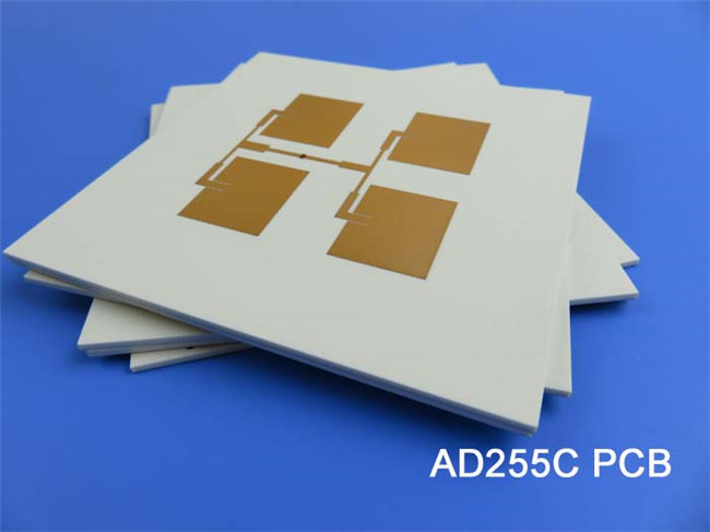
AD255C High Frequency PCB Material Introduction Hello everyone. Welcome back to our channel. Glad to have you with us again. I am Ivy, and I work as the regional sales manager for Bicheng PCB. Today we will be discussing Rogers’ AD255C antenna grade laminate and the printed circuit boards which built on this antenna materials. AD255C copper clad laminates combine the superior thermal properties of a fluoropolymer resin system with selected ceramic materials and fiberglass reinforcement, exhibiting lower loss, lower thermal expansion and lower passive intermodulation (PIM). These laminates offer the stability of PTFE over a wide range of frequencies and temperatures, making them ideal for a variety of microwave and radio frequency applications in telecommunications infrastructure. The inclusion of micro-dispersed ceramics helps to improve the thermal stability of AD255C by reducing their CTE values and improving the phase stability at different temperatures. Now let’s look at the data sheet to learn the properties of AD255C. AD255C Typical Properties One of the most impressive features of the AD255C is its PIM rating of -159/-163 dBc. Typical PIM values using reverse treated ED copper foil are -159 dBc at 30mil thickness and -163 dBc at 60mil thickness. These are typical values obtained using the extensive PIM testing capability at Rogers at 1900 MHz using a swept tone, reflected method on a 50Ω microstrip test vehicle. AD255C PCB has a dielectric constant of 2.55 (process) and 2.60 (design), which enables it to provide excellent signal transmission at high frequencies. Rogers AD255C PCB material also has an extremely low dissipation factor (0.0013) and high electrical strength (911 V/mil), further contributing to its excellent electrical performance. AD255C laminate has a thermal coefficient of dielectric constant of -110 ppm/oC at a frequency of 10 GHz over the temperature range of 0°C to 100°C as tested according to IPC TM-650. This indicates how the dielectric constant changes with temperature, and with a negative coefficient indicating that the dielectric constant decreases with increasing temperature. AD255C has a thermal coefficient of dielectric constant of -110 ppm/oC at a frequency of 10 GHz over the temperature range of 0°C to 100°C as tested according to IPC TM-650. This indicates how the dielectric constant changes with temperature, and with a negative coefficient indicating that the dielectric constant decreases with increasing temperature. Dielectric breakdown is greater than 40 kV in both the X and Y directions, as measured by D-48/50, IPC TM-650 2.5.6 In terms of thermal performance, AD255C has a decomposition temperature of >500 ?C and a thermal conductivity of 0.35 W/mK in the z direction. AD255C PCB material also has a low coefficient of thermal expansion of 34 ppm/?C (x-direction), 26 ppm/?C (y-direction) and 196 ppm/?C (z-direction) over the temperature range -55?C to 288?C range. AD255C has a delamination time of over 60 minutes at 288?C, making it an ideal material for high temperature applications. In terms of mechanical properties, AD255C has a copper peel strength of 2.4 N/mm after thermal stress, which allows it to withstand challenging environments. The material also exhibits excellent flexural strength of 8.8/6.4 MPa in machine direction and cross direction. Tensile strength in MD is 8.1 MPa and in CMD is 6.6 MPa at 23°C and 50% relative humidity as per ASTM D3039/D3039-14 standard. Flex modulus in MD is 930 MPa and in CMD is 818 MPa at 25°C as per IPC-TM-650 Test Method 2.4.4.and dimensional stability is 0.03 and 0.07 mils/inch in CD and CMD after etching and baking. In addition, AD255C has a flammability rating of V-0 grade, a low moisture absorption rate of 0.03%, a density of 2.28 g/cm3, and a specific heat capacity of 0.813 J/g°K. Electrical Properties AD255C Units Test Conditions Test Method PIM (30mil/60mil) -159/-163 dBc Reflected 43 dBm swept tones at 1900 MHz, S1/S1 Rogers Internal 50 ohm Dielectric Constant (process) 2.55 - 23°C @ 50% RH 10 GHz IPC TM-650 2.5.5.5 Dielectric Constant (design) 2.60 - C-24/23/50 10 GHz Microstrip Differential Phase Length Dissipation Factor (process) 0.0013 - 23°C @ 50% RH 10 GHz IPC TM-650 2.5.5.5 Thermal Coefficient of Dielectric Constant -110 ppm/ºC 0°C to 100°C 10 GHz IPC TM-650 2.5.5.5 Volume Resistivity 7.4 x 10⁸ Mohm-cm C-96/35/90 - IPC TM-650 2.5.17.1 Surface Resistivity 3.6 x 10⁷ Mohm C-96/35/90 - IPC TM-650 2.5.17.1 Electrical Strength (dielectric strength) 911 V/mil - - IPC TM-650 2.5.6.2 Dielectric Breakdown >40 kV D-48/50 X/Y direction IPC TM-650 2.5.6 Thermal Properties Decomposition Temperature (Td) >500 ˚C 2hrs @ 105˚C 5% Weight Loss IPC TM-650 2.3.40 Coefficient of Thermal Expansion - x 34 ppm/˚C - -55˚C to 288˚C IPC TM-650 2.4.41 Coefficient of Thermal Expansion - y 26 ppm/˚C - -55˚C to 288˚C IPC TM-650 2.4.41 Coefficient of Thermal Expansion - z 196 ppm/˚C - -55˚C to 288˚C IPC TM-650 2.4.41 Thermal Conductivity 0.35 W/mK - z direction ASTM D5470 Time to Delamination >60 minutes as-received 288˚C IPC TM-650 2.4.24.1 Mechanical Properties Copper Peel Strength after Thermal Stress 2.4 N/mm (lbs/in) 10s @288˚C 35 μm foil IPC TM-650 2.4.8 Flexural Strength (MD/CMD) 8.8/6.4 (60.7/44.1) MPa (ksi ) 25°C ± 3°C - ASTM D790 Tensile Strength (MD/CMD) 8.1/6.6 (55.8/45.5) MPa (ksi ) 23°C/50% RH - ASTM D3039/D3039-14 Flex Modulus (MD/CMD) 930/818 (6,412/5,640) MPa (ksi ) 25°C ± 3°C - IPC-TM-650 Test Method 2.4.4 Dimensional Stability (MD/CMD) 0.03/0.07 mils/inch after etch + bake - IPC-TM-650 2.4.39a Physical Properties Flammability V-0 - - - UL-94 Moisture Absorption 0.03 % E1/105 +D48/50 - IPC TM-650 2.6.2.1 Density 2.28 g/cm3 C-24/23/50 - ASTM D792 Specific Heat Capacity 0.813 J/g°K 2 hours at 105°C - ASTM E2716 PCB capability (AD255C) We provide a diverse range of PCB manufacturing capabilities to cater for the various project specifications, These include options for layer count, such as double-sided PCB, multi-layer PCB and hybrid designed boards. Copper weight options include 1oz (35μm), and 2oz (70μm), along with varying dielectric thickness options including 20mil (0.508mm), 30mil (0.762mm), 40mil (1.016mm), 60mil (1.524mm), and 125mil (3.175mm). The maximum PCB size is within 400mm X 500mm, it can be a single board of this size or multiple designs in this panel. Solder mask options include Green, Black, Blue, Yellow, Red, Purple, and more. We also offer an assortment of surface finish options, such as Immersion gold, HASL, Immersion silver, Immersion tin, OSP, ENEPIG, Bare copper, and Pure gold plated etc. PCB material: Glass-reinforced, PTFE based Composites Designation: AD255C Dielectric constant: 2.55 (10 GHz) Dissipation Factor 0.0013 (10 GHz) Layer count: Double Sided PCB, Multi-layer PCB, Hybrid PCB Copper weight: 1oz (35µm), 2oz (70µm) Dielectric thickness: 20mil (0.508mm), 30mil (0.762mm), 40mil (1.016mm), 60mil (1.524mm), 125mil (3.175mm) PCB size: ≤400mm X 500mm Solder mask: Green, Black, Blue, Yellow, Red, Purple etc. Surface Finish: Immersion gold, Hot air soldering level (HASL), Immersion silver, Immersion tin, OSP, Pure gold plated, ENEPIG, Bare copper,etc. A Piece of AD255C PCB Now displayed on the screen a 60mil AD255C PCB with immersion gold for automotive telematics antenna systems. They also perform admirably in the field of cellular infrastructure base station antenna, commercial satellite radio antenna etc. Conclusion Rogers AD255C PCBs are processed using standard equipment and chemical processes to plate, image, and etch circuit patterns. Care should be taken to preserve the post- etch laminate surface. The topography that remains after copper removal promotes improved adhesion to solder masks. Thank you for reading today's program. We hope you find the information presented here valuable and informative. Don't forget to subscribe to our channel if you find our content interesting. We look forward to seeing you again soon.
(IPC TM-650 2.5.5.3)
(13.6)


 Home
Home