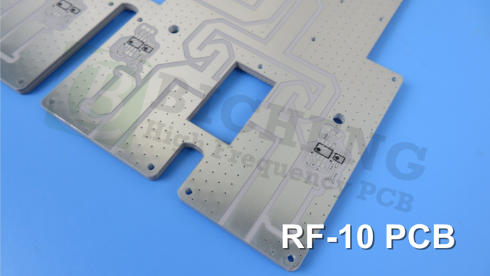
RF-10 High Frequency PCB Material Introduction Hello everyone. Today, we are thrilled to unveil Taconic RF-10 high frequency laminates, specifically engineered to deliver exceptional performance in terms of low loss and high dielectric constant (DK).RF-10 materials are meticulously crafted using a combination of ceramic-filled PTFE and woven fiberglass. To further enhance its functionality, RF-10 laminate incorporates a thin woven fiberglass reinforcement. This reinforcement not only contributes to low dielectric loss but also enhances the overall rigidity, making it easier to handle during fabrication and assembly processes. Moreover, the woven fiberglass reinforcement significantly improves the dimensional stability of multilayer circuits, ensuring consistent and reliable performance. Data Sheet In this paragraph, we delve into the remarkable characteristics of RF-10 laminates and their impact on the field of circuit board manufacturing. Electrical Properties: RF-10 laminates boast an impressive dielectric constant of 10.2 ± 0.3 at 10 GHz, ensuring efficient signal transmission and superior electrical performance. Additionally, their exceptionally low dissipation factor of 0.0025 at the same frequency ensures minimal signal loss and optimal signal integrity. These properties make RF-10 laminates highly suitable for high-frequency applications where reliable signal transmission is critical. Moreover, the surface resistivity of 1.0 x 10^8 Mohms and volume resistivity of 6.0 x 10^7 Mohms/cm further contribute to their excellent electrical characteristics. Thermal Properties Efficient heat dissipation is crucial in demanding circuitry applications, and RF-10 laminates excel in this aspect. With a thermal conductivity of 0.85 W/M*K, these laminates effectively transfer heat away from sensitive components, ensuring optimal thermal management. The coefficient of thermal expansion (CTE) of RF-10 laminates, ranging from 16 to 25 ppm/°C, ensures compatibility with copper, minimizing stress and potential failures due to thermal cycling. Additionally, the TcDK rating of -370 ppm/°C over a temperature range of -55 to 150 °C further reminds designers to pay attention to whether RF-10 is suitable for use in environments with large temperature changes in their product. Mechanical Properties: RF-10 laminates exhibit outstanding mechanical strength. With flexural strength values of 96.53 N/mm^2 (MD) and 68.95 N/mm^2 (CD), they offer robustness and reliability during fabrication and assembly processes. Their tensile strength of 62.57 N/mm^2 (MD) and 37.26 N/mm^2 (CD) further ensures durability and integrity in demanding environments. Additionally, RF-10 laminates demonstrate excellent dimensional stability, exhibiting minimal changes in size and shape during etching, baking, and stress conditions, as evidenced by the precise % (25 mil-MD/CD) and % (60 mil-MD/CD) values. Chemical/Physical Properties: RF-10 laminates exhibit desirable chemical and physical properties. With a moisture absorption rate of 0.08%, they remain stable even under humid conditions. The peel strength of 1.7 N/mm for soldered 1 oz. RT copper ensures strong adhesion, vital for reliable connections. Furthermore, their density specific gravity of 2.77 g/cm^3 and specific heat of 0.90 J/g°C contribute to their overall performance and handling characteristics. Notably, they possess a flammability rating of V-0, ensuring compliance with stringent safety standards. Typical Value Properties Conditions RF-10 Unit Test Method Electrical Properties Dielectric Constant @ 10 GHz 10.2 ± 0.3 IPC-650 2.5.5.5.1 Mod. Dissipation Factor @ 10 GHz 0.0025 IPC-650 2.5.5.5.1 Mod. Surface Resistivity 1.0 x 10^8 Mohms IPC-650 2.5.17.1 Volume Resistivity 6.0 x 10^7 Mohms/cm IPC-650 2.5.17.1 Thermal Properties Thermal Conductivity Unclad 0.85 W/M*K IPC-650-2.4.50 CTE (RT- 150 °C) X 16 ppm/°C IPC-650 2.4.41 Y 20 Z 25 TcDK (-55 to 150 °C) -370 ppm/°C IPC-650 2.5.5.6 Mechanical Properties Flexural Strength MD 96.53 (14,000) N/mm2 (psi) IPC-650-2.4.4 CD 68.95 (10,000) N/mm2 (psi) Tensile Strength MD 62.57 (8,900) N/mm2 (psi) IPC-650-2.4.19 CD 37.26 (5,300) N/mm2 (psi) Dimensional Stability -0.0032 % (25 mil-MD) IPC-650 2.4.39 (After Etch) -0.0215 % (25 mil-MD) IPC-650 2.4.39 (After Bake) Dimensional Stability -0.0301 % (25 mil-MD) IPC-650 2.4.39 (After Stress) -0.0027 % (60 mil-MD) IPC-650 2.4.39 (After Etch) Dimensional Stability -0.1500 % (60 mil-MD) IPC-650 2.4.39 (After Bake) -0.0167 % (60 mil-MD) IPC-650 2.4.39 (After Stress) Chemical / Physical Properties Moisture Absorption 0.08 % IPC-650 2.6.2.1 Peel Strength 1.7 N/mm IPC-650 2.4.8 (solder) Density Specific Gravity 2.77 g/cm3 IPC-650-2.3.5 Specific Heat 0.90 J/g°C IPC-650-2.4.50 Flammability Rating V-0 Internal PCB Capability (RF-10) We excel in providing double-sided PCBs, multilayer PCBs, and hybrid PCBs, offering you the flexibility to choose the most suitable option for your specific design requirements. You can select from our diverse range of copper weights, including 0.5oz (17 µm), 1oz (35 µm), and 2oz (70 µm), ensuring optimal electrical conductivity and performance based on your project needs. We offer a range of thickness options, including 10mil (0.254mm), 20mil (0.508mm), 25mil (0.635mm), 60mil (1.524mm), and 125mil (3.175mm), allowing you to select the appropriate thickness for your project. Our manufacturing capabilities support PCBs with dimensions up to 400mm X 500mm, providing flexibility in accommodating your desired board size. You have the option to choose from various solder mask colors such as Green, Black, Blue, Yellow, Red, and more, allowing for visual customization and easy identification. We offer a wide range of surface finish options, including Bare Copper, HASL, ENIG, Immersion Silver, Immersion Tin, OSP, Pure Gold, ENEPIG, and more. This ensures compatibility with different assembly processes and enhances the solderability and durability of the PCB. PCB Capability (RF-10) PCB Material: Composites of Ceramic Filled PTFE and Woven Fiberglass Designation: RF-10 Dielectric constant: 10.2 Dissipation Factor 0.0025 10GHz Layer count: Double Sided PCB, Multilayer PCB, Hybrid PCB Copper weight: 0.5oz (17 µm), 1oz (35µm), 2oz (70µm) PCB thickness: 10mil (0.254mm), 20mil (0.508mm), 25mil (0.635mm), 60mil (1.524mm), 125mil ( 3.175mm ) PCB size: ≤400mm X 500mm Solder mask: Green, Black, Blue, Yellow, Red etc. Surface finish: Bare copper, HASL, ENIG, Immersion silver, Immersion tin, OSP, Pure gold, ENEPIG etc.. RF-10 PCB and Applications On the screen, we are currently viewing a 2-layer RF-10 PCB featuring immersion silver on a 60mil substrate. Taconic RF-10 PCBs are widely used in various applications, including microstrip patch antennas, GPS antennas, passive components, aircraft collision avoidance systems, satellite components, and more. Final Machining of ceramic/PTFE substrates is typically more difficult than epoxy-based substrates due to the softness of the PTFE resin system. The style of fiberglass used in the substrate also affects the quality of routing with respect to burrs and fibers. The heavier the fiberglass weave, the more difficult it is to cut. Taconic RF-10 ceramic/PTFE laminates can be successfully machined using two flute end mills when the recommended methods and rout parameters are used. Rigid Phenolic entry and a rigid backer should be used. In some cases, adding paper (white paper or Kraft paper) between the Phenolic and the part allows better conformance to surface topography (e.g. circuits, soldermask, etc.) and may reduce burring. For tight tolerances or superior edge quality, a “rough cut” placed 0.005 in. -0.010 in. off the part edge may be run prior to the “finish” cut at the nominal part edge. That concludes today’s topic. Thanks for reading. We’ll see you next time.
-0.0239
% (25 mil-CD)
-0.0529
% (25 mil-CD)
-0.0653
% (25 mil-CD)
-0.0142
% (60 mil-CD)
-0.0326
% (60 mil-CD)
-0.0377
% (60 mil-CD)
(1 oz. RT copper)


 Home
Home