

 Home
-
Microwave PCB
-
TF1020 High DK10.2 PCB 25mil Thickness Double Sided Copper Immersion Gold PCB for Microwave and Millimeter-Wave Applications
Home
-
Microwave PCB
-
TF1020 High DK10.2 PCB 25mil Thickness Double Sided Copper Immersion Gold PCB for Microwave and Millimeter-Wave Applications
TF1020 High DK10.2 PCB 25mil Thickness Double Sided Copper Immersion Gold PCB for Microwave and Millimeter-Wave Applications
Printed Circuit Boards are custom-made products; the images and specifications provided are for reference only.
Brief Introduction
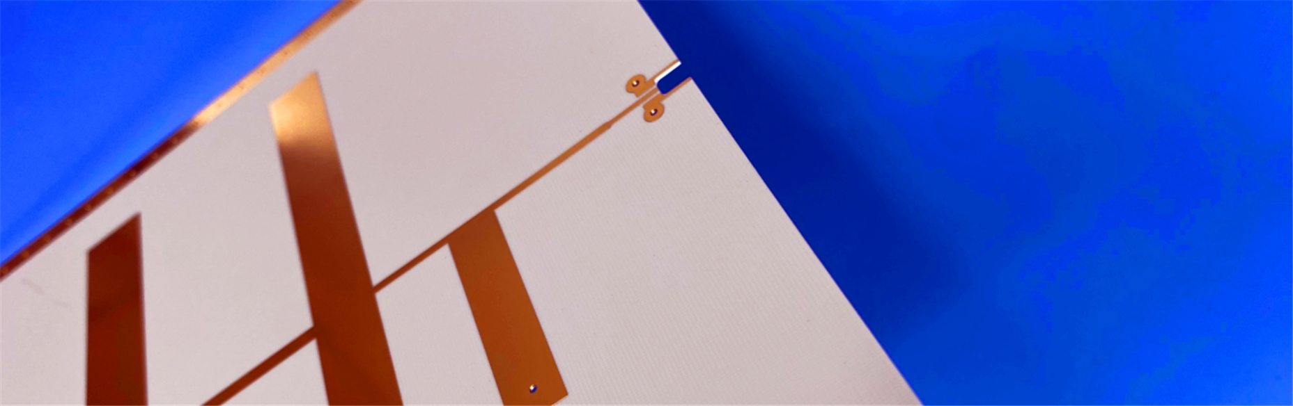
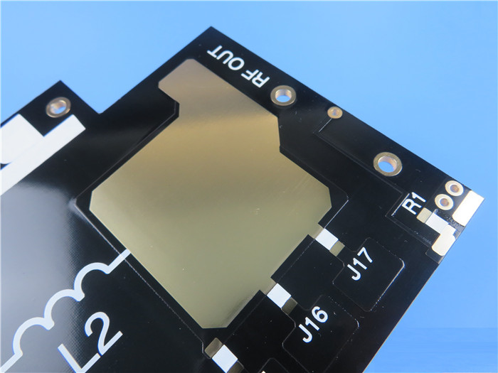
This TF1020 high-frequency PCB is a double-sided circuit board designed for demanding microwave and millimeter-wave applications. Featuring a 0.635mm (25mil) TF1020 core material with high dielectric constant (10.2), TF1020 PCB board measures 105mm × 72mm in a single-up panel configuration. The TF1020 PCB construction utilizes 1oz copper layers on both top and bottom surfaces, starting from 0.5oz base copper, and is finished with immersion gold surface treatment and black solder mask on the top layer. TF1020 circuit board exclusively supports surface-mount components, making it ideal for high-frequency designs requiring consistent electrical performance.
Here are more specific detail in table below.
PCB Specifications
| TF1020 High Frequency PCB 25mil Double Sided Alternative High DK 10.2 Substrates With Immersion Gold | |
| PCB SIZE | 105 x 72mm=1up |
| BOARD TYPE | Double sided PCB |
| Number of Layers | 2 layers |
| Surface Mount Components | YES |
| Through Hole Components | NO |
| LAYER STACKUP | copper ------- 35um(0.5 oz+plate) TOP layer |
| TF1020 - 0.635mm | |
| copper ------- 35um(0.5 oz + plate) BOT Layer | |
| TECHNOLOGY | |
| Minimum Trace and Space: | 10 mil / 12 mil |
| Minimum / Maximum Holes: | 0.4 mm / 3.2 mm |
| Number of Different Holes: | 6 |
| Number of Drill Holes: | 18 |
| Number of Milled Slots: | 1 |
| Number of Internal Cutouts: | 0 |
| Impedance Control: | no |
| Number of Gold finger: | 0 |
| BOARD MATERIAL | |
| Glass Epoxy: | TF1020 DK 10.2 |
| Final foil external: | 1.0 oz |
| Final foil internal: | N/A |
| Final height of PCB: | 0.7 mm ±0.1 |
| PLATING AND COATING | |
| Surface Finish | Immersion Gold |
| Solder Mask Apply To: | Top layer |
| Solder Mask Color: | Black |
| Solder Mask Type: | LPI |
| CONTOUR/CUTTING | Routing |
| MARKING | |
| Side of Component Legend | N/A |
| Colour of Component Legend | N/A |
| Manufacturer Name or Logo: | N/A |
| VIA | Plated through hole(PTH), minimum size 0.4mm. |
| FLAMIBILITY RATING | 94V-0 |
| DIMENSION TOLERANCE | |
| Outline dimension: | 0.0059"" |
| Board plating: | 0.0029"" |
| Drill tolerance: | 0.002"" |
| TEST | 100% Electrical Test prior shipment |
| TYPE OF ARTWORK TO BE SUPPLIED | email file, Gerber RS-274-X, PCBDOC etc |
| SERVICE AREA | Worldwide, Globally. |
TF Series High Frequency Laminates
The TF series laminates represent advanced composite materials combining microwave-grade PTFE resin with ceramic fillers, specifically engineered without fiberglass cloth reinforcement. This unique TF material formulation allows precise dielectric constant control through careful adjustment of the ceramic-to-PTFE ratio. TF1020 PCB demonstrates exceptional dielectric properties and reliability through specialized manufacturing processes. The product line includes TF (base material without copper cladding), TF-1 (single-sided copper cladding), and TF-2 (double-sided copper cladding) variants, providing design flexibility for various high-frequency applications including millimeter-wave radar sensors, antenna systems, transceivers, modulators, multiplexers, power supply equipment, and automated control systems.
Our PCB Capability (TF series)
PCB Capability (TF Series) |
|||
PCB Material: |
Polyphenylene ether, ceramic |
||
Designation (TF Series) |
Designation |
DK |
DF |
|
TF300 |
3.0±0.06 |
0.0010 |
|
TF440 |
4.4±0.09 |
0.0010 |
|
TF600 |
6.0±0.12 |
0.0010 |
|
TF615 |
6.15±0.12 |
0.0010 |
|
TF920 |
9.2±0.18 |
0.0010 |
|
TF960 |
9.6±0.19 |
0.0012 |
|
TF1020 |
10.2±0.2 |
0.0012 |
|
TF1600 |
16.0±0.4 |
0.0014 |
Layer count: |
Single Sided, Double Sided PCB |
||
Copper weight: |
1oz (35µm), 2oz (70µm) |
||
Dielectric thickness (Dielectric thickness or overall thickness) |
0.635mm, 0.8mm, 1.0mm, 1.2mm, 1.5mm, 2.0mm, 2.5mm |
||
PCB size: |
≤240mm X 240mm |
||
Solder mask: |
Green, Black, Blue, Yellow, Red etc. |
||
Surface finish: |
Bare copper, HASL, ENIG, Immersion silver, Immersion tin, OSP, Pure gold, ENEPIG etc.. |
||
TF Data Sheet