

 Home
-
Microwave PCB
-
TF Series High Frequency PCB PTFE Ceramic Composite Adjusted DK Microwave Substrate
Home
-
Microwave PCB
-
TF Series High Frequency PCB PTFE Ceramic Composite Adjusted DK Microwave Substrate
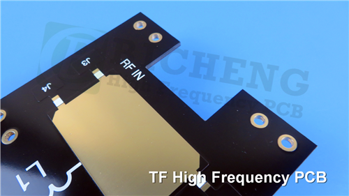
TF Series High Frequency PCB PTFE Ceramic Composite Adjusted DK Microwave Substrate
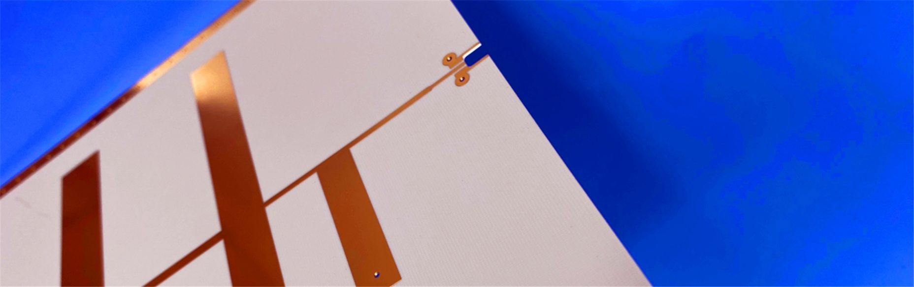
Printed Circuit Boards are custom-made products; the images and specifications provided are for reference only.
General Description
Dielectric substrate of PTFE ceramic composite - TF
The TF Series represents a premium class of high-frequency circuit laminates engineered for demanding microwave applications. These innovative materials combine temperature-resistant polytetrafluoroethylene (PTFE) resin with precisely formulated ceramic composites, creating an optimal substrate solution for high-frequency designs.
As a fiberglass-free construction, TF laminates achieve exceptional dielectric consistency and performance stability. The dielectric constant is meticulously controlled through precise adjustment of the ceramic-to-PTFE ratio, enabling customized electrical properties for specific application requirements. This unique formulation, coupled with specialized manufacturing processes, delivers outstanding dielectric performance and remarkable reliability in challenging operating environments.
The TF product family includes three distinct configurations to meet diverse design needs: TF base material features a smooth surface without copper cladding, TF-1 provides single-sided copper cladding, while TF-2 offers double-sided copper cladding. This comprehensive range ensures designers can select the optimal material configuration for their specific high-frequency circuit applications, from simple structures to complex multilayer designs.
These advanced TF series laminates are particularly suitable for microwave and millimeter-wave printed circuit boards, including applications in radar systems, antenna designs, transceivers, and various RF components where consistent electrical performance and material reliability are paramount.
Features
- The dielectric constant ranges from 3 to 16 and is stable, including 3.0, 6.0, 9.2, 9.6, 10.2, and 16, with low dielectric loss.
- Used for the fabrication of microwave and millimeter-wave printed circuit boards.
- Long-term working temperature is higher than TP materials and can be used in the range of -80°C to +200°C.
- Thickness options range from 0.635mm to 2.5mm.
- Resistant to radiation and low outgassing.
- Convenient for PCB processing, can be processed using methods suitable for thermoplastic materials.
Our PCB Capability (TF Series)
PCB Capability (TF Series) |
|||
PCB Material: |
Polyphenylene ether, ceramic |
||
Designation (TF Series) |
Designation |
DK |
DF |
|
TF300 |
3.0±0.06 |
0.0010 |
|
TF440 |
4.4±0.09 |
0.0010 |
|
TF600 |
6.0±0.12 |
0.0010 |
|
TF615 |
6.15±0.12 |
0.0010 |
|
TF920 |
9.2±0.18 |
0.0010 |
|
TF960 |
9.6±0.19 |
0.0012 |
|
TF1020 |
10.2±0.2 |
0.0012 |
|
TF1600 |
16.0±0.4 |
0.0014 |
Layer count: |
Single Sided, Double Sided PCB |
||
Copper weight: |
1oz (35µm), 2oz (70µm) |
||
Dielectric thickness (Dielectric thickness or overall thickness) |
0.635mm, 0.8mm, 1.0mm, 1.2mm, 1.5mm, 2.0mm, 2.5mm |
||
PCB size: |
≤240mm X 240mm |
||
Solder mask: |
Green, Black, Blue, Yellow, Red etc. |
||
Surface finish: |
Bare copper, HASL, ENIG, Immersion silver, Immersion tin, OSP, Pure gold, ENEPIG etc.. |
||
Data Sheet (TF Series)
| Product Technical Parameter | Product Models & Data Sheet | ||||||||||||
| Product Features | Test Conditions | Unit | TF TF-1 TF-2 | ||||||||||
| Dielectric Constant | When the dielectric constant is ≤11, the test condition is 10GHz. When the dielectric constant is >11, the test condition is 5GHz. |
/ | 3.0±0.06 | 4.4±0.09 | |||||||||
| 6.0±0.12 | 6.15±0.12 | ||||||||||||
| 9.2±0.18 | 9.6±0.19 | ||||||||||||
| 10.2±0.2 | 16.0±0.4 | ||||||||||||
| The dielectric constant can be customized within the range of 3.0~16 | |||||||||||||
| Tolerance of Dielectric Constant | Dielectric Constant 3.0~11.0 | / | ±2% | ||||||||||
| Dielectric Constant 11.1~16.0 | / | ±2.5% | |||||||||||
| Loss Tangent | Dielectric Constant 3.0~9.5 | 10GHz | / | 0.0010 | |||||||||
| Dielectric Constant 9.6~11.0 | 10GHz | / | 0.0012 | ||||||||||
| Dielectric Constant 11.1~16.0 | 5GHz | / | 0.0014 | ||||||||||
| Dielectric Constant Temperature Coefficient | Dielectric Constant 3.0~4.5 | -55 º~150ºC | PPM/℃ | -60 | |||||||||
| Dielectric Constant 6.0~6.5 | -55 º~150ºC | PPM/℃ | -210 | ||||||||||
| Dielectric Constant 9.0~11.0 | -55 º~150ºC | PPM/℃ | -260 | ||||||||||
| Dielectric Constant 12.0~16.0 | -55 º~150ºC | PPM/℃ | -205 | ||||||||||
| Peel Strength | 1 OZ Normal State | N/mm | >0.6 | ||||||||||
| 1 OZ After AC Humidity Test | N/mm | >0.4 | |||||||||||
| Volume Resistivity | Normal State 500V | MΩ.cm | >1×10^9 | ||||||||||
| Surface Resistivity | Normal State 500V | MΩ | >1×10^7 | ||||||||||
| Coefficient of Thermal Expansion (XY Z) |
Dielectric Constant 3.00~6.15 | -55 º~150ºC | PPM/℃ | 60,60,80 | |||||||||
| Dielectric Constant 6.16~11.0 | -55 º~150ºC | PPM/℃ | 50,50,65 | ||||||||||
| Dielectric Constant 11.1~16.0 | -55 º~150ºC | PPM/℃ | 40,40,55 | ||||||||||
| Water Absorption | 20±2℃, 24 hours | % | ≤0.05 | ||||||||||
| Long-Term Operating Temperature | High-Low Temperature Chamber | ℃ | -80~200ºC | ||||||||||
| Material Composition | Polytetrafluoroethylene (PTFE), ceramic, paired with ED copper foil. | ||||||||||||
| The density and thermal conductivity data for materials with different dielectric constants are as follows: | |||||||||||||
| Product Features | Unit | Dielectric Constant | |||||||||||
| 3.0 | 4.4 | 6.0 | 6.15 | 9.2 | 9.6 | 10.2 | 16.0 | ||||||
| Density | g/cm3 | 2.41 | 2.58 | 2.78 | 2.79 | 3.0 | 3.02 | 3.07 | 3.27 | ||||
| Thermal Conductivity | W/(M.K) | 0.30 | 0.32 | 0.45 | 0.46 | 0.66 | 0.68 | 0.7 | 0.75 | ||||