
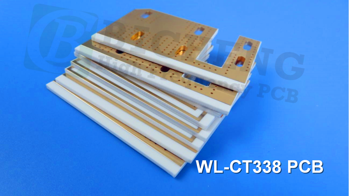
WL-CT High Frequency PCB Material Introduction The WL-CT series of organic polymer ceramic fiberglass cloth-covered copper boards is a thermosetting resin-based high-frequency material. The composition of the dielectric layer includes hydrocarbon resin, ceramics, and fiberglass cloth. It exhibits low loss performance, meeting the requirements for high-frequency designs. PCB processing can be carried out using techniques similar to FR4 materials, making it simpler compared to PTFE materials and ensuring better stability and consistency in circuitry. It can be used as a substitute for similar foreign products. The combination of hydrocarbon resin and composite ceramics provides excellent low loss, high-temperature resistance, and temperature stability characteristics. The series of materials have a stable temperature coefficient of dielectric constant and loss, low thermal expansion coefficient, and a high TG value of above 280°C. The series offers a selection of dielectric constants: 3.00, 3.30, 3.38, 3.48, 4.10, and 6.15. These materials can be paired with standard ED copper foil or reverse-treated RTF copper foil. RTF copper foil offers excellent PIM (Passive Intermodulation) performance, reducing conductor loss and insertion loss. The back-treated RTF copper foil has an increased material thickness of 0.018mm (0.7mil), providing good adhesion. The series can also be paired with aluminum-based substrates to create aluminum-based high-frequency materials. The circuit boards can be processed using standard FR4 board fabrication techniques. The excellent mechanical and physical properties of the material allow for multiple lamination cycles, making it suitable for multi-layer, high-layer-count, and backplane processing. It exhibits excellent processability in dense hole and fine line routing. Product Features: The combination of hydrocarbon resin and composite ceramics provides excellent low loss, high-temperature resistance, and temperature stability characteristics. The series of materials have a stable temperature coefficient of dielectric constant and loss, low thermal expansion coefficient, and a high TG value of above 280°C. The series offers a selection of dielectric constants: 3.00, 3.30, 3.38, 3.48, 4.10, and 6.15. These materials can be paired with standard ED copper foil or reverse-treated RTF copper foil. RTF copper foil offers excellent PIM (Passive Intermodulation) performance, reducing conductor loss and insertion loss. The back-treated RTF copper foil has an increased material thickness of 0.018mm (0.7mil), providing good adhesion. The series can also be paired with aluminum-based substrates to create aluminum-based high-frequency materials. The circuit boards can be processed using standard FR4 board fabrication techniques. The excellent mechanical and physical properties of the material allow for multiple lamination cycles, making it suitable for multi-layer, high-layer-count, and backplane processing. It exhibits excellent processability in dense hole and fine line routing. Product Models & Data Sheet Let’s explore the data sheet one by one: Product Models WL-CT300 WL-CT330 WL-CT330Z WL-CT338 WL-CT350 WL-CT440 WL-CT61 Dielectric Constant (Typical): Test Conditions: 10GHz WL-CT300: 3.00 WL-CT330: 3.30 WL-CT330Z: 3.30 WL-CT338: 3.38 WL-CT350: 3.48 WL-CT440: 4.10 WL-CT615: 6.1 Dielectric Constant (Design): Test Conditions: 10GHz WL-CT300: 2.98 WL-CT330: 3.45 WL-CT330Z: 3.45 WL-CT338: 3.55 WL-CT350: 3.66 WL-CT440: 4.38 WL-CT615: 6.4 Dielectric Constant Tolerance: WL-CT300: ±0.05 WL-CT330: ±0.06 WL-CT330Z: ±0.06 WL-CT338: ±0.05 WL-CT350: ±0.05 WL-CT440: ±0.08 WL-CT615: ±0.15 Loss Tangent (Typical): Test Conditions: 2GHz 10GHz 20GHz WL-CT300: 0.0025 / 0.0030 / 0.0036 WL-CT330: 0.0021 / 0.0026 / 0.0033 WL-CT330Z: 0.0025 / 0.0030 / 0.0035 WL-CT338: 0.0023 / 0.0029 / 0.0038 WL-CT350: 0.0030 / 0.0039 / 0.0048 WL-CT440: 0.0040 / 0.0050 / / WL-CT615: 0.0032 / 0.0040 / / Dielectric Constant Temperature Coefficient: Test Conditions: -55 ºC to 150ºC Unit: PPM/℃ WL-CT300: 27 WL-CT330: 43 WL-CT330Z: 43 WL-CT338: 45 WL-CT350: 52 WL-CT440: -21 WL-CT615: -122 Peel Strength: Test Conditions: 1 OZ RTF copper Unit: N/mm WL-CT300: 0.85 WL-CT330: 1.0 WL-CT330Z: 0.85 WL-CT338: 1.0 WL-CT350: 0.85 WL-CT440: 1.0 WL-CT615: 0.9 Volume Resistivity Test Conditions: Standard Condition Unit: MΩ.cm WL-CT300: 3×10^8 WL-CT330: 5×10^9 WL-CT330Z: 5×10^9 WL-CT338: 6×10^9 WL-CT350: 1×10^9 WL-CT440: 1×10^9 WL-CT615: 2×10^ Surface Resistivity: Test Conditions: Standard Condition Unit: MΩ WL-CT300: 2×10^8 WL-CT330: 5×10^9 WL-CT330Z: 5×10^9 WL-CT338: 7×10^8 WL-CT350: 4×10^9 WL-CT440: 5×10^7 WL-CT615: 5×10^6 Electrical Strength (Z direction): Test Conditions: 5KW, 500V/s Unit: KV/mm WL-CT300: 28 WL-CT330: 22 WL-CT330Z: 22 WL-CT338: 31 WL-CT350: 31 WL-CT440: 27 WL-CT615: 30 Breakdown Voltage (XY direction): Test Conditions: 5KW, 500V/s Unit: KV WL-CT300: 35 WL-CT330: 22 WL-CT330Z: 22 WL-CT338: 30 WL-CT350: 30 WL-CT440: 25 WL-CT615: 25 Coefficient of Thermal Expansion (X, Y direction): Test Conditions: -55 ºC to 288ºC Unit: ppm/ºC WL-CT300: 15, 14 WL-CT330: 15, 13 WL-CT330Z: 15, 13 WL-CT338: 14, 16 WL-CT350: 11, 14 WL-CT440: 14, 18 WL-CT615: 15, 17 Coefficient of Thermal Expansion (Z direction): Test Conditions: -55 ºC to 288ºC Unit: ppm/ºC WL-CT300: 31 WL-CT330: 39 WL-CT330Z: 39 WL-CT338: 50 WL-CT350: 34 WL-CT440: 35 WL-CT615: 33 Thermal Stress: Test Conditions: 288℃, 10s, 3 times Result: No Delamination Water Absorption: Test Conditions: 20±2℃, 24 hours Unit: % WL-CT300: 0.15 WL-CT330: 0.02 WL-CT330Z: 0.05 WL-CT338: 0.04 WL-CT350: 0.05 WL-CT440: 0.12 WL-CT615: 0.08 Density: Test Conditions: Room Temperature Unit: g/cm3 WL-CT300: 1.57 WL-CT330: 1.82 WL-CT330Z: 1.78 WL-CT338: 1.78 WL-CT350: 1.90 WL-CT440: 2.00 WL-CT615: 2.18 Long-Term Operating Temperature: Test Conditions: High-Low Temperature Chamber Unit: ℃ WL-CT300: -55 to +260 WL-CT330: -55 to +260 WL-CT330Z: -55 to +260 WL-CT338: -55 to +260 WL-CT350: -55 to +260 WL-CT440: -55 to +260 WL-CT615: -55 to +260 Flammability: Test Conditions: UL 94 WL-CT300: V-0 WL-CT330: V-0 WL-CT330Z: V-0 WL-CT338: V-0 WL-CT350: V-0 WL-CT440: V-0 WL-CT615: V-0 Product Technical Parameters Product Models & Data Sheet Product Features Test Conditions Unit WL-CT300 WL-CT330 WL-CT330Z WL-CT338 WL-CT350 WL-CT440 WL-CT615 Dielectric Constant (Typical) 10GHz / 3.00 3.30 3.30 3.38 3.48 4.10 6.15 Dielectric Constant (Design) 10GHz / 2.98 3.45 3.45 3.55 3.66 4.38 6.4 Dielectric Constant Tolerance / / ±0.05 ±0.06 ±0.06 ±0.05 ±0.05 ±0.08 ±0.15 Loss Tangent (Typical) 2GHz / 0.0025 0.0021 0.0025 0.0023 0.0030 0.0040 0.0032 10GHz / 0.0030 0.0026 0.0030 0.0029 0.0039 0.0050 0.0040 20GHz / 0.0036 0.0033 0.0035 0.0038 0.0048 / / Dielectric Constant Temperature Coefficient -55 º~150ºC PPM/℃ 27 43 43 45 52 -21 -122 Peel Strength 1 OZ RTF copper N/mm 0.85 1.0 0.85 1.0 0.85 1.0 0.9 1 OZ RTFcopper N/mm 0.72 0.72 0.72 0.72 0.72 Not compatible Not compatible Volume Resistivity Standard Condition MΩ.cm 3×10^8 5×10^9 5×10^9 6×10^9 1×10^9 1×10^9 2×10^7 Surface Resistivity Standard Condition MΩ 2×10^8 5×10^9 5×10^9 7×10^8 4×10^9 5×10^7 5×10^6 Electrical Strength (Z direction) 5KW,500V/s KV/mm 28 22 22 31 31 27 30 Breakdown Voltage (XY direction) 5KW,500V/s KV 35 22 22 30 30 25 25 Coefficientof Thermal Expansion (X, Y direction) -55 º~288ºC ppm/ºC 15, 14 15, 13 15, 13 14, 16 11, 14 14, 18 15, 17 Coefficientof Thermal Expansion (Z direction) -55 º~288ºC ppm/ºC 31 39 39 50 34 35 33 Thermal Stress 288℃, 10s,3 times / No Delamination No Delamination No Delamination No Delamination No Delamination No Delamination No Delamination Water Absorption 20±2℃, 24 hours % 0.15 0.02 0.05 0.04 0.05 0.12 0.08 Density Room Temperature g/cm3 1.57 1.82 1.78 1.78 1.90 2.00 2.18 Long-Term Operating Temperature High-Low Temperature Chamber ℃ -55~+260 -55~+260 -55~+260 -55~+260 -55~+260 -55~+260 -55~+260 Thermal Conductivity Z direction W/(M.K) 0.41 0.59 0.59 0.70 0.70 0.66 0.72 PIM Paired with RTF copper foil. dBc ≤-158 ≤-157 ≤-157 ≤-158 ≤-157 N/A N/A Flammability UL-94 Grade V-0 Non-flame retardant V-0 Non-flame retardant V-0 V-0 V-0 TG Standard ℃ >280℃ >280℃ >280℃ >280℃ >280℃ >280℃ >280℃ TD Initial Value ℃ 412 421 386 421 386 402 398 Halogen Yes No Yes No Yes Yes No Material Composition Hydrocarbon + Ceramic + Fiberglass cloth Our PCB Capability (WL-CT) Our capabilities include the following specifications: Layer count: We can manufacture single-sided, double-sided PCBs, as well as multilayer PCBs and hybrid PCBs. Copper weight: We offer options for copper weight, including 1oz (35µm) and 2oz (70µm). Dielectric thickness: For ED Copper: 4mil (with no TRF Copper) 8mil with TRF Copper of 8.7mil 12mil (with no TRF Copper) 16mil (with no TRF Copper) 20mil with TRF Copper of 20.7mil 28mil (with no TRF Copper) 32mil with TRF Copper of 32.7mil 40mil with TRF Copper of 40.7mil 60mil with TRF Copper of 60.7mil 80mil with TRF Copper of 80.7mil PCB size: We can accommodate PCB sizes up to 400mm X 500mm. Solder mask: We offer a range of solder mask colors such as green, black, blue, yellow, red, and more. Surface finish: Our surface finish options include bare copper, HASL (Hot Air Solder Leveling), ENIG (Electroless Nickel Immersion Gold), immersion silver, immersion tin, OSP (Organic Solderability Preservative), pure gold, ENEPIG (Electroless Nickel Electroless Palladium Immersion Gold), and more. PCB Capability (WL-CT Series) PCB Material: Hydrocarbon resin, ceramic, and glass fiber cloth Designation (WL-CT Series) Designation DK DF WL-CT300 3.0±0.05 0.0030 WL-CT330 3.3±0.06 0.0026 WL-CT330Z 3.3±0.06 0.0030 WL-CT338 3.38±0.05 0.0029 WL-CT350 3.48±0.05 0.0039 WL-CT440 4.1±0.08 0.0050 WL-CT615 6.15±0.15 0.0040 Layer count: Single Sided, Double Sided PCB, Multilayer PCB, Hybrid PCB Copper weight: 1oz (35µm), 2oz (70µm) Dielectric thickness ED Copper TRF Copper 4mil / 8mil 8.7mil 12mil / 16mil / 20mil 20.7mil 28mil / 32mil 32.7mil 40mil 40.7mil 60mil 60.7mil 80mil 80.7mil PCB size: ≤400mm X 500mm Solder mask: Green, Black, Blue, Yellow, Red etc. Surface finish: Bare copper, HASL, ENIG, Immersion silver, Immersion tin, OSP, Pure gold, ENEPIG etc.. A WL-CT PCB and Applications Displayed on the screen is a double-sided 1.6mm WL-CT338 PCB with immersion gold coating specifically designed for filters. WL-CT PCBs are versatile and widely used in various applications, including: Base station antennas and satellite antennas. Automotive radar, sensors, and navigation systems. Power amplifiers. Satellite high-frequency heads. RF devices and filters. WIMAX antennas and distributed antennas. Small-sized patch antennas. Final (WL-CT series aluminum-based boards) This series of laminates provides aluminum-based substrates, where one side of the dielectric layer is covered with copper foil, and the other side is covered with an aluminum-based layer. It serves for shielding or heat dissipation purposes. The model numbers are WL-CT***-AL. For instance, WL-CT350-AL represents WL-CT350 with an aluminum-based substrate.


 Home
Home