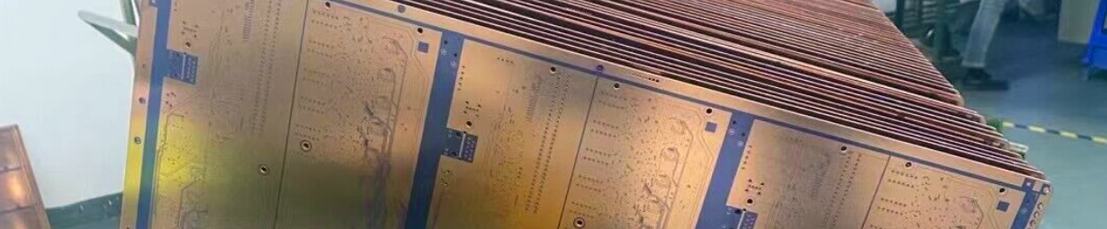
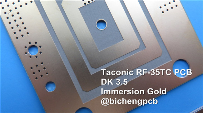
RF-35TC High Frequency PCB Material Introduction Hello everyone. Welcome back to our channel. Today, we’re going to introduce the high frequency PCB built on thermally conductive low loss material ---- RF-35TC PCB. RF-35TC is a PTFE based, ceramic filled fiberglass laminate from Taconic company. It will not oxidize, yellow or show upward drift in dielectric constant and dissipation factor. Taconic RF-35TC laminate provides low dissipation factor with high thermal conductivity. The heat is diffused away from both transmission lines and surface mount components such as capacitors etc. RF-35 Typical Properties First, let's talk about the dielectric properties of the RF-35TC. The DK at 10 GHz is 3.5 which is a low value in most high frequency PCBs. The DK is stable across a broad temperature range which is critical for both narrow band and broad band overlay couplers. Furthermore, the TCDk value remains consistent at 24 ppm across a wide temperature range from -30 to 120℃, ensuring stable performance. Moving on to the RF-35TC's electrical properties, we have a low Df value of 0.0011 at 10 GHz, indicating minimal signal loss and high signal integrity, whereas RT/duroid 6035HTC is 0.0013, TC600 is 0.0017 and TC350 is 0.002. The dielectric breakdown and dielectric strength are impressive, measuring at 56.7 kV and 570 V/mil (22,441 V/mm) respectively. The RF-35TC material exhibits exceptional arc resistance, surpassing industry standards with an impressive duration of 304 seconds, as determined by IPC-650 2.5.1.Dielectric breakdown is 56.7 kilo voltages, dielectric strength is 570 V/mil. These are secure value for our electronics devices. With a moisture absorption rate of a mere 0.05%, the RF-35TC material showcases outstanding resistance to absorbing moisture, complying with the stringent IPC-650 2.6.2.1 standard. This ensures its reliability and stability even in environments with high humidity or exposure to moisture. Let's now discuss the mechanical properties of the RF-35TC laminate. It exhibits excellent flexural strength, with values of 12,900 psi (88.94 N/mm2) in the MD direction and 11,700 psi (80.67 N/mm2) in the CD direction. Similarly, the tensile strength measures at 9,020 psi (62.19 N/mm2) and 7,740 psi (53.37 N/mm2) in the MD and CD directions respectively. The RF-35TC also demonstrates good elongation at break, with 1.89% (1.89 N/mm) in the MD direction and 1.7% in the CD direction. Additionally, it has a high Young's modulus, measuring at 667,000 psi (4,599 N/mm2) and 637,000 psi (4,392 N/mm2) in the MD and CD directions respectively. Now, let's move on to the RF-35TC's thermal properties. It exhibits excellent thermal conductivity, with values of 0.6 W/(mK) at 125℃ for both the unclad condition and the C1/C1 configuration. The CH/CH configuration has a slightly lower thermal conductivity of 0.87 W/(mK) at the same temperature. The extremely low Df and high thermal conductivity are particularly suited for power amplifier applications. Another important property to consider is the material's dimensional stability. The RF-35TC shows minimal dimensional changes, with values of 0.23 mils/in. (0.23 mm/M) and 0.64 mils/in. (0.64 mm/M) in the MD and CD directions, respectively, after etching. Under thermal stress, the changes are even smaller, with -0.04 mils/in. (-0.04 mm/M) in the MD direction and 0.46 mils/in. (0.46 mm/M) in the CD direction. In terms of electrical properties, the RF-35TC maintains good surface resistivity after elevated temperature and humidity, measuring at 8.33 x 10^7 Mohms and 6.42 x 10^7 Mohms, respectively. Similarly, it maintains good volume resistivity under the same conditions, measuring at 5.19 x 10^8 Mohms/cm and 2.91 x 10^8 Mohms/cm, respectively. Now let's quickly cover a few more properties. The RF-35TC has a low coefficient of thermal expansion (CTE) in all three axes, measuring at 11 and 13 ppm/℃ in the X and Y axes, and 34 ppm/℃ in the Z axis. Low X and Y CTE values are crucial for maintaining critical distances between trace elements in printed filters,enhancing antenna gains and efficiencies. The density is 2.35 g/cm3, and the material has a hardness of 79.1 (ASTM D 2240, Shore D). Lastly, the RF-35TC exhibits a specific heat of 0.94 j/(g℃) and has a thermal decomposition temperature (Td) of 420℃ (788°F) for a 2% weight loss and 436℃ (817°F) for a 5% weight loss. Property Test Method Unit RF-35TC Unit RF-35TC DK at 10 GHz IPC-650 2.5.5.5.1(modified) 3.5 3.5 Tck(-30 to 120℃) IPC-650 2.5.5.5.1(modified) ppm 24 ppm 24 Df at 10 GHz IPC-650 2.5.5.5.1(modified) 0.0011 0.0011 Dielectric Breakdown IPC-650 2.5.6(in-Plane,Two Pins in Oil) kV 56.7 kV 56.7 Dielectric Strength ASTM D 149(Through Plane) V/mil 570 V/mm 22,441 Arc Resistance IPC-650 2.5.1 Seconds 304 Seconds 304 Moisture Absorption IPC-650 2.6.2.1 % 0.05 % 0.05 Flexural Strength(MD) ASTM D 790/IPC-650 2.4.4 psi 12,900 N/mm2 88.94 Flexural Strength(CD) ASTM D 790/IPC-650 2.4.4 psi 11,700 N/mm2 80.67 Tensile Strength(MD) ASTM D 3039/IPC-TM-650 2.4.19 psi 9,020 N/mm2 62.19 Tensile Strength(CD) ASTM D 3039/IPC-TM-650 2.4.19 psi 7,740 N/mm2 53.37 Elongation at Break(MD) ASTM D 3039/IPC-TM-650 2.4.19 % 1.89 N/mm 1.89 Elongation at Break(CD) ASTM D 3039/IPC-TM-650 2.4.19 % 1.7 % 1.7 Young's Modulus(MD) ASTM D 3039/IPC-TM-650 2.4.19 psi 667,000 N/mm2 4,599 Young's Modulus(CD) ASTM D 3039/IPC-TM-650 2.4.19 psi 637,000 N/mm2 4,392 Poisson's Ratio(MD) ASTM D 3039/IPC-TM-650 2.4.19 0.18 0.18 Poisson's Ratio(CD) ASTM D 3039/IPC-TM-650 2.4.19 0.23 0.18 Compressive Modulus ASTM D 695(23℃) psi 560,000 N/mm2 3,861 Flexural Strength(MD) ASTM D 790/IPC-650 2.4.4 psi 1.46 x 10⁶ N/mm2 10,309 Flexural Strength(CD) ASTM D 790/IPC-650 2.4.4 psi 1.50 x 10⁶ N/mm2 10,076 Peel Stength(½ oz.CVH) IPC-650 2.4.8(Thermal Stress.) Ibs./inch 7 g/cm3 1.25 Thermal Conductivity(Unclad,125℃) ASTM F433(Guarded Heat Flow) W/(mK) 0.6 W/(mK) 0.6 Thermal Conductivity(C1/C1,125℃) ASTM F433(Guarded Heat Flow) W/(mK) 0.92 W/(mK) 0.92 Thermal Conductivity(CH/CH,125℃) ASTM F433(Guarded Heat Flow) W/(mK) 0.87 W/(mK) 0.87 Dimensional Stability(MD) IPC-650-2.4.39 Sec.5.4(After Etch) mils/in. 0.23 mm/M 0.23 Dimensional Stability(CD) IPC-650-2.4.39 Sec.5.4(After Etch) mils/in. 0.64 mm/M 0.64 Dimensional Stability(MD) IPC-650-2.4.39 Sec.5.5(Thermal Stress.) mils/in. -0.04 mm/M -0.04 Dimensional Stability(CD) IPC-650-2.4.39 Sec.5.5(Thermal Stress.) mils/in. 0.46 mm/M 0.46 Surface Resistivity IPC-650 2.5.17.1(after elevated temp.) Mohms 8.33 x 10⁷ Mohms 8.33 x 10⁷ Surface Resistivity IPC-650 2.5.17.1(after humidity) Mohms 6.42 x 10⁷ Mohms 6.42 x 10⁷ Volume Resistivity IPC-650 2.5.17.1(after elevated temp.) Mohms/cm 5.19 x 10⁸ Mohms/cm 5.19 x 10⁸ Volume Resistivity IPC-650 2.5.17.1(after humidity) Mohms/cm 2.91 x 10⁸ Mohms/cm 2.91 x 10⁸ CTE(X axis)(25-260℃) IPC-650 2.4.41/ASTM D 3386 ppm/℃ 11 ppm/℃ 11 CTE(Y axis)(25-260℃) IPC-650 2.4.41/ASTM D 3386 ppm/℃ 13 ppm/℃ 13 CTE(Z axis)(25-260℃) IPC-650 2.4.41/ASTM D 3386 ppm/℃ 34 ppm/℃ 34 Density ASTM D 792 g/cm3 2.35 g/cm3 2.35 Hardness ASTM D 2240(Shore D) 79.1 79.1 Strain at Break(MD) ASTM D 790/IPC-650 2.4.4 % 0.014 % 0.014 Strain at Break(CD) ASTM D 790/IPC-650 2.4.4 % 0.013 % 0.013 Specific Heat ASTM E 1269-05,E 967-08,E968-02 j/(g℃) 0.94 j/(g℃) 0.94 Td(2% Weight Loss) IPC-650 2.4.24.6/TGA oF 788 ℃ 420 Td(5% Weight Loss) IPC-650 2.4.24.6/TGA oF 817 ℃ 436 PCB Capability (RF-35TC) Now, let’s take a look at our PCB capabilities on RF-35TC material. For RF-35TC PCBs, we can provide you with single layer board, double layer board, multi-layer board and hybrid types. Taconic RF-35TC PCBs have wide thickness. These are the standard thickness such as 10 mils, 20 mils, 30 mils, and 60mils etc. Finished copper on PCB can be 1oz and 2oz. Our maximum PCB size on high frequency materials is 400mm by 500mm, it can be a single board in the sheet and also can be different designs in this panel. Solder mask of green, black, blue and yellow etc is available in house. There’s immersion gold, HASL, immersion silver, immersion tin, bare copper etc. for pads plating. PCB material: PTFE based Ceramic filled Fiberglass Designation: RF-35TC Dielectric constant: 3.50 @ 10GHz Layer count: 1-layer, 2-layer, Multi-layer, Hybrid type Dielectric thickness: 5mil (0.127mm), 10mil (0.254mm), 20mil (0.508mm), 30mil (0.762mm), 60mil (1.524mm) Copper weight: 1oz, 2oz Solder mask: Green, Black, Blue, Yellow, White etc. PCB size: ≤400mm X 500mm Surface finish: Immersion gold, HASL, Immersion silver, Immersion tin, Bare copper, OSP, Pure gold, ENEPIG etc. A Piece of RF-35TC PCB The basic colour of RF-35TC PCB is brown and gray. On the screen is a type of 30mil RF-35TC PCB with immersion gold and black solder mask for filters. We can also see the applications in couplers, antennas, power amplifiers and satellite equipment etc. Conclusion Like most material properties, there are many techniques for measuring thermal conductivity. Thermal conductivity measured on an unclad laminate offers the true thermal conductivity of the material. Measurements on a copper clad laminate (CCL) typically yield higher values as the CCL offers the least thermal resistance at the interface between the laminate and measuring equipment. When measured with or without copper cladding, RF-35TC PCB offers superior heat dissipation performance. Well, this conclude today’s episode. Thank you for reading. See you next time.


 Home
Home