
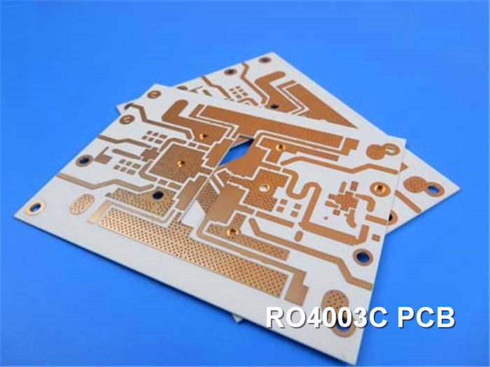
R04003C High Frequency PCB Material Introduction Greetings, everyone! Welcome back to our channel. In today's episode, we will be discussing high frequency PCBs constructed using RO4003C laminates. Rogers RO4003C PCB materials are a unique blend of woven glass reinforced hydrocarbon/ceramics, offering electrical performance comparable to PTFE/woven glass while maintaining the manufacturing advantages of epoxy/glass. Rogers 4003 laminate PCBs are available in various configurations, incorporating both 1080 and 1674 glass fabric styles. Regardless of the configuration, all RO4003C laminates meet the same high standard of electrical performance. With RO4003C laminates, you can achieve precise control over the dielectric constant (Dk) and experience low loss, all while benefiting from the cost advantages compared to traditional microwave laminates. Unlike microwave materials based on PTFE, there is no need for special through-hole treatments or handling procedures when working with RO4003C laminates. It is important to note that Rogers RO4003C materials are non-brominated and do not possess a UL 94 V-0 rating. Data Sheet The dielectric constant (εProcess) for RO4003C is 3.38±0.05 in the Z direction at 10 GHz and 23℃. The measurement is conducted using the IPC-TM-650 2.5.5.5 Clamped Stripline test method. The dielectric constant (εDesign) for RO4003C is 3.55 in the Z direction within the frequency range of 8 to 40 GHz. This measurement is determined using the Differential Phase Length Method. The dissipation factor for RO4003C is 0.0027 at 10 GHz and 23℃, and 0.0021 at 2.5 GHz and 23℃. The measurement is performed according to the IPC-TM-650 2.5.5.5 test method. The thermal coefficient of the dielectric constant (ε) for RO4003C is +40 ppm/℃ in the Z direction over a temperature range of -50℃ to 150℃. The measurement is conducted using the IPC-TM-650 2.5.5.5 test method. The volume resistivity of RO4003C laminate is 1.7 x 10^10 MΩ.cm under Condition A. This measurement is performed according to the IPC-TM-650 2.5.17.1 test method. The surface resistivity of RO4003C is 4.2 x 10^9 MΩ under Condition A. The measurement is conducted using the IPC-TM-650 2.5.17.1 test method. The electrical strength of RO4003C is 31.2 KV/mm (780 V/mil) in the Z direction with a thickness of 0.508?mm (0.020"). This measurement is performed according to the IPC-TM-650 2.5.6.2 test method. The tensile modulus of RO4003C is 19,650 MPa (2,850 ksi) in the X direction and 19,450 MPa (2,821 ksi) in the Y direction at room temperature. The measurement is conducted according to ASTM D 638. The tensile strength of RO4003C is 139 MPa (20.2 ksi) in the X direction and 100 MPa (14.5 ksi) in the Y direction at room temperature. This measurement is performed according to ASTM D 638. The flexural strength of RO4003C is 276 MPa (40 kpsi). The measurement is conducted using the IPC-TM-650 2.4.4 test method. The dimensional stability of RO4003C is less than 0.3 mm/m (mil/inch) in the X and Y directions after etch and exposure to E2 at 150℃. This measurement is performed according to the IPC-TM-650 2.4.39A test method. The coefficient of thermal expansion for .Rogers 4003 PCB is 11 ppm/℃ in the X direction, 14 ppm/℃ in the Y direction, and 46 ppm/℃ in the Z direction over a temperature range of -55℃ to 288℃. The measurement is conducted using the IPC-TM-650 2.4.41 test method. The glass transition temperature (Tg) of RO4003C is greater than 280℃, determined by the TMA (Thermomechanical Analysis) method according to IPC-TM-650 2.4.24.3. The decomposition temperature (Td) of RO4003C is 425℃, determined by the TGA (Thermogravimetric Analysis) method according to ASTM D 3850. The thermal conductivity of RO4003C is 0.71 W/M/oK at 80℃, measured according to ASTM C518. The moisture absorption of RO4003C is 0.06% after 48 hours of immersion at a temperature of 50℃. This measurement is performed according to ASTM D 570. The density of RO4003C is 1.79 gm/cm3 at 23℃, determined by ASTM D 792. The copper peel strength of RO4003C is 1.05 N/mm (6.0 pli) after solder float with 1 oz. EDC Foil. The measurement is conducted according to the IPC-TM-650 2.4.8 test method. The flammability rating for RO4003C is not available. Finally, RO4003C is compatible with lead-free processes. RO4003C Typical Value Property RO4003C Direction Units Condition Test Method Dielectric Constant,εProcess 3.38±0.05 Z 10 GHz/23℃ IPC-TM-650 2.5.5.5 Clamped Stripline Dielectric Constant,εDesign 3.55 Z 8 to 40 GHz Differential Phase Length Method Dissipation Factortan,δ 0.0027 Z 10 GHz/23℃ IPC-TM-650 2.5.5.5 Thermal Coefficient of ε +40 Z ppm/℃ -50℃to 150℃ IPC-TM-650 2.5.5.5 Volume Resistivity 1.7 x 10¹⁰ MΩ.cm COND A IPC-TM-650 2.5.17.1 Surface Resistivity 4.2 x 10⁹ MΩ COND A IPC-TM-650 2.5.17.1 Electrical Strength 31.2(780) Z Kv/mm(v/mil) 0.51mm(0.020") IPC-TM-650 2.5.6.2 Tensile Modulus 19,650(2,850) X MPa(ksi) RT ASTM D 638 Tensile Strength 139(20.2) X MPa(ksi) RT ASTM D 638 Flexural Strength 276 MPa IPC-TM-650 2.4.4 Dimensional Stability <0.3 X,Y mm/m after etch+E2/150℃ IPC-TM-650 2.4.39A Coefficient of Thermal Expansion 11 X ppm/℃ -55℃to288℃ IPC-TM-650 2.4.41 Tg >280 ℃ TMA A IPC-TM-650 2.4.24.3 Td 425 ℃ TGA ASTM D 3850 Thermal Conductivity 0.71 W/M/oK 80℃ ASTM C518 Moisture Absorption 0.06 % 48hrs immersion 0.060" ASTM D 570 Density 1.79 gm/cm3 23℃ ASTM D 792 Copper Peel Stength 1.05 N/mm after solder float 1 oz. IPC-TM-650 2.4.8 Flammability N/A UL 94 Lead-free Process Compatible Yes PCB Capability (RO4003C) In terms of our PCB manufacturing capability, we offer the following options: We can produce single-layer, double-layer, multilayer, and hybrid configuration PCBs. This allows us to accommodate a wide range of design requirements, from simple single-layer boards to complex multilayer configurations. We provide options for copper weight on the PCBs. You can choose between 1oz (35µm) or 2oz (70µm) copper weight, depending on your specific needs for electrical conductivity and thermal dissipation. We offer various thickness options for the PCBs, including 8mil (0.203mm), 12mil (0.305mm), 16mil (0.406mm), 20mil (0.508mm), 32mil (0.813mm), and 60mil (1.524mm). The selection of PCB thickness depends on your application and design requirements. Our manufacturing capabilities support PCB sizes up to ≤400mm X 500mm. This allows us to handle a range of board sizes, from small to medium-sized boards. We provide a variety of solder mask colors, such as green, black, blue, yellow, red, and more. You can choose the solder mask color that best suits your design aesthetics or specific preferences. We offer multiple surface finish options for the PCBs, including bare copper, HASL (Hot Air Solder Leveling), ENIG (Electroless Nickel Immersion Gold), OSP (Organic Solderability Preservative), immersion tin, immersion silver, ENEPIG (Electroless Nickel Electroless Palladium Immersion Gold), pure gold, and more. The choice of surface finish depends on factors like solderability, corrosion resistance, and cost considerations. PCB Material: Hydrocarbon Ceramic Laminates Designation: RO4003C Dielectric constant: 3.38±0.05 at 10GHz Layer count: Single layer, Double layer, Multilayer, Hybrid configuration Copper weight: 1oz (35µm), 2oz (70µm) PCB thickness: 8mil (0.203mm), 12mil (0.305mm), 16mil (0.406mm), 20mil(0.508mm), 32mil (0.813mm), 60mil(1.524mm) PCB size: ≤400mm X 500mm Solder mask: Green, Black, Blue, Yellow, Red etc. Surface finish: Bare copper, HASL, ENIG, OSP, Immersion tin, Immersion silver, ENEPIG, Pure gold etc.. A PCB and Applications Displayed on the screen is a 20mils thick RO4003C PCB with an immersion gold surface finish, which is custom-tailored for antenna applications. Rogers RO4003C PCB is widely utilized across diverse industries, encompassing base station antennas, power amplifiers, RF identification tags, automotive radar, sensors, and more. The production of multi-layer circuit boards using RO4003C PCB involves combining multiple cores through bondply RO4450F. To strike a balance between cost-effectiveness and minimizing signal loss in high-frequency environments, the concept of incorporating high-frequency materials with FR-4 emerged. Currently, the manufacturing technology for hybrid circuit boards has reached a mature stage, leading to their growing popularity in the market.
0.0021
2.5 GHz/23℃
19,450(2,821)
Y
100(14.5)
Y
(40)
(kpsi)
(mil/inch)
14
46
Y
Z
sample Temperature 50℃
(6.0)
(pli)
EDC Foil


 Home
Home