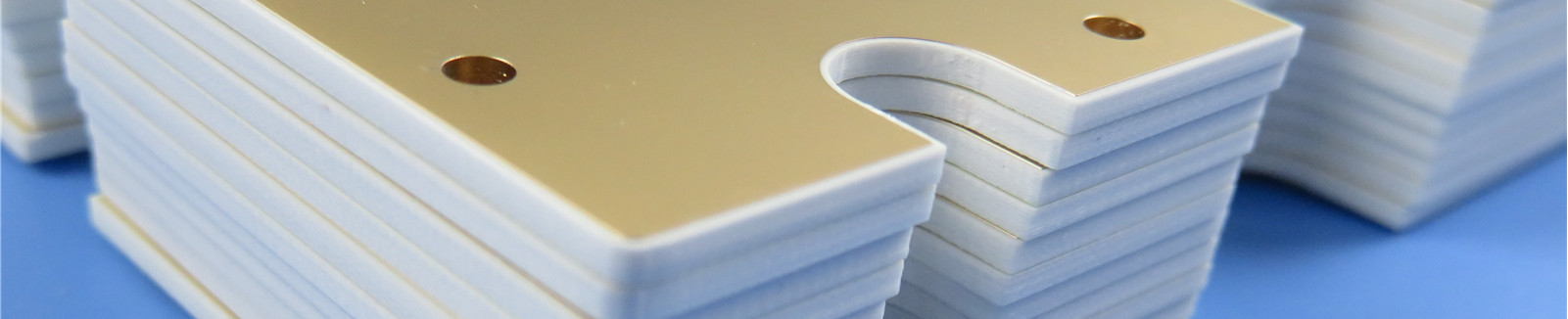
Low Profile RO4003C High Frequency PCB Material Introduction RO4003C LoPro laminates use a proprietary Rogers' technology that allows reverse treated foil to bond to standard RO4003C dielectric. This results in a laminate with low conductor loss for improved insertion loss and signal integrity while maintaining all other desirable attributes of the standard RO4003C laminate system. Features and Benefits: Rogers RO4003C PCB materials are reinforced hydrocarbon/ceramic laminates with very low profile reverse treated foil. 1. Lower insertion loss 2. Low PIM 3. Increased signal integrity 4. High circuit density Low Z-axis coefficient of thermal expansion 1. Multi-layer board capability 2. Design flexibility Lead-free process compatible 1. High temperature processing 2. Meets environmental concerns CAF resistant Some Typical Applications: Digital applications such as servers, routers, and high speed back planes Cellular base station antennas and power amplifiers LNB’s for direct broadcast satellites RF Identification Tags Our PCB Capability (RO4003C LoPro) PCB Material: Hydrocarbon Ceramic Laminates Designation: RO4003C LoPro Dielectric constant: 3.38±0.05 Layer count: Double Layer, Multilayer, Hybrid PCB Copper weight: 0.5oz (17 μm), 1oz (35μm), 2oz (70μm) Laminate thickness: 12.7mil (0.323mm), 16.7mil (0.424mm), 20.7mil(0.526mm), 32.7mil (0.831mm), 60.7mil(1.542mm) PCB size: ≤400mm X 500mm Solder mask: Green, Black, Blue, Yellow, Red etc. Surface finish: Bare copper, HASL, ENIG, OSP, Immersion Tin, Immersion Silver etc.. Typical Properties of RO4003C LoPro Property Typical Value Direction Units Condition Test Method Dielectric Constant, Process 3.38 ± 0.05 Z -- 10 GHz/23°C IPC-TM-650 2.5.5.5 Clamped Stripline Dielectric Constant, Design 3.5 Z -- 8 to 40 GHz Differential Phase Length Method Dissipation Factor tan, d 0.0027 0.0021 Z -- 10 GHz/23°C 2.5 GHz/23°C IPC-TM-650 2.5.5.5 Thermal Coeffifi cient of er 40 Z ppm/°C -50°C to 150°C IPC-TM-650 2.5.5.5 Volume Resistivity 1.7 X 10^10 MΩ-cm COND A IPC-TM-650 2.5.17.1 Surface Resistivity 4.2 X 10^9 MΩ COND A IPC-TM-650 2.5.17.1 Electrical Strength 31.2(780) Z KV/mm(V/mil) 0.51mm(0.020”) IPC-TM-650 2.5.6.2 Tensile Modulus 26889(3900) Y MPa(kpsi) RT ASTM D638 Tensile Strength 141(20.4) Y MPa(kpsi) RT ASTM D638 Flexural Strength 276(40) MPa(kpsi) IPC-TM-650 2.4.4 Dimensional Stability <0.3 X,Y mm/m(mils/inch) after etch +E2/150°C IPC-TM-650 2.4.39A Coeffifi cient of Thermal Expansion 11 X ppm/°C -55 to 288°C IPC-TM-650 2.1.41 14 Y 46 Z Tg >280 °C TMA A IPC-TM-650 2.4.24.3 Td 425 °C TGA ASTM D3850 Thermal Conductivity 0.64 W/m/°K 80°C ASTM C518 Moisture Absorption 0.06 % 48 hrs immersion 0.060” sample Temperature 50°C ASTM D570 Density 1.79 gm/cm3 23°C ASTM D792 Copper Peel Strength 1.05(6.0) N/mm(pli) after solder float 1 oz. TC Foil IPC-TM-650 2.4.8 Flammability N/A UL 94 Lead-Free Process Compatible Yes 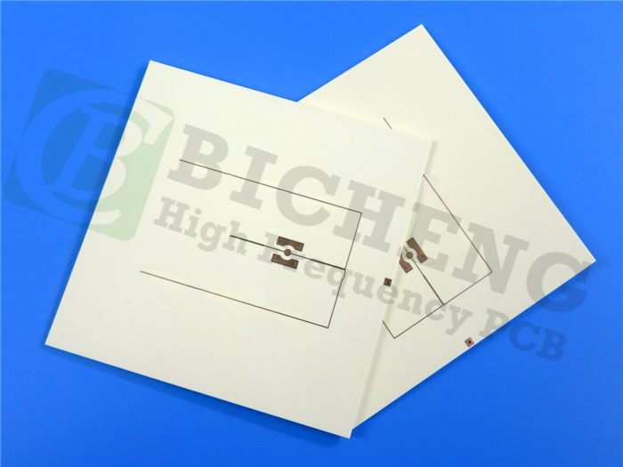


 Home
Home