

 Home
-
Hybrid PCB
-
Rogers RO3003 and RO3210 3-Layer 3.0mm Hybrid PCB High-Frequency laminate for Automotive Radar and 5G Infrastructure
Home
-
Hybrid PCB
-
Rogers RO3003 and RO3210 3-Layer 3.0mm Hybrid PCB High-Frequency laminate for Automotive Radar and 5G Infrastructure
Rogers RO3003 and RO3210 3-Layer 3.0mm Hybrid PCB High-Frequency laminate for Automotive Radar and 5G Infrastructure
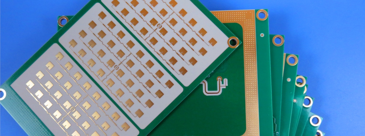
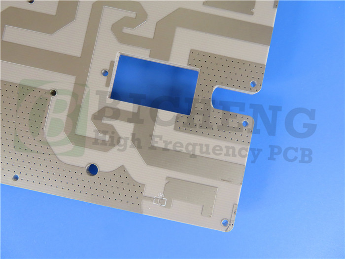
Printed Circuit Boards are custom-made products; the images and specifications provided are for reference only.
Overview
This product is a specialized 3-layer rigid printed circuit board (PCB) engineered for demanding high-frequency and RF applications. Rogers RO3003 and RO3210 Hybrid PCB utilizes a hybrid construction of Rogers RO3003 and RO3210 high-frequency laminates, combining superior electrical performance with enhanced mechanical stability. Designed with precise dimensions of 62.8mm x 62.8mm and a substantial 3.0mm thickness, this hybrid PCB is built to meet the stringent requirements of modern wireless systems, including automotive radar and 5G infrastructure. The board features a sophisticated layer stackup with blind vias, is supplied with Gerber RS-274-X artwork, and is 100% electrically tested to ensure reliability and performance, conforming to IPC-Class-2 standards.
PCB Construction Details
Parameter |
Specification |
Base Material |
RO3003 and RO3210 mixed |
Layer Count |
3 layers |
Board Dimensions |
62.8mm x 62.8mm (+/- 0.15mm) |
Minimum Trace/Space |
7/9 mils |
Minimum Hole Size |
0.4mm |
Via Type |
Blind vias (Inner layer 2 to Bottom layer) |
Finished Board Thickness |
3.0mm |
Finished Cu Weight (Outer) |
1 oz (1.4 mils / 35 μm) |
Via Plating Thickness |
20 μm |
Surface Finish |
Immersion Tin |
Silkscreen (Top/Bottom) |
No |
Solder Mask (Top/Bottom) |
No |
Electrical Test |
100% tested prior to shipment |
Additional Components & Features
Rogers RO3003 and RO3210 Hybrid PCB is designed to accommodate a compact assembly with 21 components. The layout includes 47 total pads, comprising 35 thru-hole pads and 12 surface-mount pads on the top side, interconnected by 24 vias across 4 nets. The specific stackup is meticulously engineered: a 35μm Copper Layer 1 on a 1.524mm RO3003 core, bonded via a 0.101mm RO4450F prepreg to a 35μm Copper Layer 2, which is on a 1.27mm RO3210 core, and finally a 35μm Copper Layer 3.
Material Advantages
The hybrid PCB material selection provides distinct benefits. The RO3003 laminate, with a stable dielectric constant (Dk) of 3.00 and a low dissipation factor of 0.001, ensures minimal signal loss and consistent performance across temperature variations, which is critical for mmWave applications. The RO3210 laminate, with a higher Dk of 10.2, offers excellent mechanical rigidity due to its woven fiberglass reinforcement and a CTE matched to copper, enhancing board reliability. Both materials feature a high decomposition temperature (Td > 500°C), making them robust during assembly and in operation.
Typical Applications
Rogers RO3003 and RO3210 Hybrid PCB is ideally suited for a range of high-performance applications, including automotive collision avoidance systems (e.g., 77 GHz radar), Advanced Driver Assistance Systems (ADAS), automotive GPS antennas, 5G wireless infrastructure and base stations, microstrip patch antennas, direct broadcast satellites, and wireless broadband systems like LMDS.
Why Choose This PCB?
This board offers a reliable, high-performance solution for complex RF designs by leveraging the proven advantages of Rogers materials. Its construction is tailored for signal integrity and thermal management, supported by full electrical testing and worldwide availability, ensuring it meets the quality and performance demands of critical communications and automotive systems.
Order Now for Advanced Automotive and 5G Systems!
Secure this high-frequency PCB to power your next-generation radar and telecommunications products. Contact us today to discuss your project requirements and leverage this robust, high-performance solution.