

 Home
-
High Temperature PCB
-
WL-CT Series High-Frequency PCB: Advanced Organic Polymer Ceramic-Based Circuit Board Solution with High TG above 280
Home
-
High Temperature PCB
-
WL-CT Series High-Frequency PCB: Advanced Organic Polymer Ceramic-Based Circuit Board Solution with High TG above 280
WL-CT Series High-Frequency PCB: Advanced Organic Polymer Ceramic-Based Circuit Board Solution with High TG above 280
Printed Circuit Boards are custom-made products; the images and specifications provided are for reference only.
Brief Introduction
The WL-CT series represents a cutting-edge line of organic polymer ceramic fiberglass cloth-covered copper boards, engineered as thermosetting resin-based high-frequency materials. These innovative circuit materials combine hydrocarbon resin, ceramic composites, and fiberglass cloth in their dielectric layer composition, delivering exceptional low-loss performance that meets the demanding requirements of advanced high-frequency designs.
A significant advantage of WL-CT PCB materials lies in their processing compatibility with standard FR4 manufacturing techniques, offering substantially simpler fabrication processes compared to conventional PTFE materials while ensuring superior circuit stability and consistency. This domestic solution serves as an excellent substitute for imported high-frequency materials in various applications.
The unique combination of hydrocarbon resin and composite ceramics provides outstanding electrical and thermal properties, including:
Excellent low-loss characteristics
High-temperature resistance capabilities
Remarkable temperature stability
Stable temperature coefficient of dielectric constant
Low thermal expansion coefficient
High Tg value exceeding 280°C
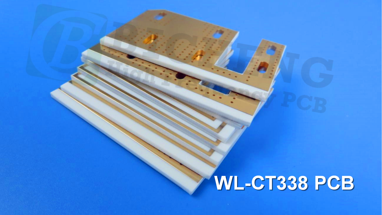
The series offers multiple dielectric constant options including 3.00, 3.30, 3.38, 3.48, 4.10, and 6.15, providing design flexibility for various application requirements. These materials are compatible with both standard ED copper foil and reverse-treated RTF copper foil, with RTF copper foil delivering exceptional Passive Intermodulation (PIM) performance while reducing conductor loss and insertion loss. The back-treated RTF copper foil features an increased material thickness of 0.018mm (0.7mil), ensuring superior adhesion properties.
Additionally, the WL-CT series PCB can be combined with aluminum substrates to create high-performance aluminum-based high-frequency materials. The excellent mechanical and physical properties enable multiple lamination cycles, making these materials ideally suited for multilayer constructions, high-layer-count boards, and backplane processing applications. The series demonstrates exceptional processability for dense via patterns and fine line routing, supporting the most demanding high-frequency circuit designs.
Product Features
- Low dielectric constant tolerance and low loss.
- Thermosetting resin-based system with improved PCB processability and heat resistance.
- Excellent temperature coefficient of dielectric constant with minimal temperature variation.
- Thermal expansion coefficients in the X/Y directions equivalent to copper foil; low thermal expansion coefficient in the Z direction ensures dimensional stability and reliable copper connections in the holes.
- High TG value above 280°C, maintaining dimensional stability and copper quality even at high temperatures.
- High thermal conductivity, superior to thermoplastic materials of the same grade, suitable for high-power applications.
- Commercialized, mass-produced, cost-effective products.
- Excellent resistance to radiation, maintaining stable dielectric and physical properties even after exposure to radiation.
- Low outgassing performance, meeting the vacuum outgassing requirements for aerospace applications.
Product Models & Data Sheet
| Product Technical Parameters | Product Models & Data Sheet | ||||||||
| Product Features | Test Conditions | Unit | WL-CT300 | WL-CT330 | WL-CT330Z | WL-CT338 | WL-CT350 | WL-CT440 | WL-CT615 |
| Dielectric Constant (Typical) | 10GHz | / | 3.00 | 3.30 | 3.30 | 3.38 | 3.48 | 4.10 | 6.15 |
| Dielectric Constant (Design) | 10GHz | / | 2.98 | 3.45 | 3.45 | 3.55 | 3.66 | 4.38 | 6.4 |
| Dielectric Constant Tolerance | / | / | ±0.05 | ±0.06 | ±0.06 | ±0.05 | ±0.05 | ±0.08 | ±0.15 |
| Loss Tangent (Typical) | 2GHz | / | 0.0025 | 0.0021 | 0.0025 | 0.0023 | 0.0030 | 0.0040 | 0.0032 |
| 10GHz | / | 0.0030 | 0.0026 | 0.0030 | 0.0029 | 0.0039 | 0.0050 | 0.0040 | |
| 20GHz | / | 0.0036 | 0.0033 | 0.0035 | 0.0038 | 0.0048 | / | / | |
| Dielectric Constant Temperature Coefficient | -55 º~150ºC | PPM/℃ | 27 | 43 | 43 | 45 | 52 | -21 | -122 |
| Peel Strength | 1 OZ RTF copper | N/mm | 0.85 | 1.0 | 0.85 | 1.0 | 0.85 | 1.0 | 0.9 |
| 1 OZ RTFcopper | N/mm | 0.72 | 0.72 | 0.72 | 0.72 | 0.72 | Not compatible | Not compatible | |
| Volume Resistivity | Standard Condition | MΩ.cm | 3×10⁸ | 5×10⁹ | 5×10⁹ | 6×10⁹ | 1×10⁹ | 1×10⁹ | 2×10⁷ |
| Surface Resistivity | Standard Condition | MΩ | 2×10⁸ | 5×10⁹ | 5×10⁹ | 7×10⁸ | 4×10⁹ | 5×10⁷ | 5×10⁶ |
| Electrical Strength (Z direction) | 5KW,500V/s | KV/mm | 28 | 22 | 22 | 31 | 31 | 27 | 30 |
| Breakdown Voltage (XY direction) | 5KW,500V/s | KV | 35 | 22 | 22 | 30 | 30 | 25 | 25 |
| Coefficientof Thermal Expansion (X, Y direction) | -55 º~288ºC | ppm/ºC | 15,14 | 15,13 | 15, 13 | 14, 16 | 11, 14 | 14, 18 | 15, 17 |
| Coefficientof Thermal Expansion (Z direction) | -55 º~288ºC | ppm/ºC | 31 | 39 | 39 | 50 | 34 | 35 | 33 |
| Thermal Stress | 288℃, 10s,3 times | / | No Delamination | No Delamination | No Delamination | No Delamination | No Delamination | No Delamination | No Delamination |
| Water Absorption | 20±2℃, 24 hours | % | 0.15 | 0.02 | 0.05 | 0.04 | 0.05 | 0.12 | 0.08 |
| Density | Room Temperature | g/cm3 | 1.57 | 1.82 | 1.78 | 1.78 | 1.90 | 2.00 | 2.18 |
| Long-Term Operating Temperature | High-Low Temperature Chamber | ℃ | -55~+260 | -55~+260 | -55~+260 | -55~+260 | -55~+260 | -55~+260 | -55~+260 |
| Thermal Conductivity | Z direction | W/(M.K) | 0.41 | 0.59 | 0.59 | 0.70 | 0.70 | 0.66 | 0.72 |
| PIM | Paired with RTF copper foil. | dBc | ≤-158 | ≤-157 | ≤-157 | ≤-158 | ≤-157 | N/A | N/A |
| Flammability | UL-94 | Grade | V-0 | Non-flame retardant | V-0 | Non-flame retardant | V-0 | V-0 | V-0 |
| TG | Standard | ℃ | >280℃ | >280℃ | >280℃ | >280℃ | >280℃ | >280℃ | >280℃ |
| TD | Initial Value | ℃ | 412 | 421 | 386 | 421 | 386 | 402 | 398 |
| Halogen | Yes | No | Yes | No | Yes | Yes | No | ||
| Material Composition | Hydrocarbon + Ceramic + Fiberglass cloth |
Our PCB Capability (WL-CT)
| PCB Capability (WL-CT Series) | |||
| PCB Material: | Hydrocarbon resin, ceramic, and glass fiber cloth | ||
| Designation (WL-CT Series) | Designation | DK | DF |
| WL-CT300 | 3.0±0.05 | 0.0030 | |
| WL-CT330 | 3.3±0.06 | 0.0026 | |
| WL-CT330Z | 3.3±0.06 | 0.0030 | |
| WL-CT338 | 3.38±0.05 | 0.0029 | |
| WL-CT350 | 3.48±0.05 | 0.0039 | |
| WL-CT440 | 4.1±0.08 | 0.0050 | |
| WL-CT615 | 6.15±0.15 | 0.0040 | |
| Layer count: | Single Sided, Double Sided PCB, Multilayer PCB, Hybrid PCB | ||
| Copper weight: | 1oz (35µm), 2oz (70µm) | ||
| Dielectric thickness | ED Copper | TRF Copper | |
| 4mil | / | ||
| 8mil | 8.7mil | ||
| 12mil | / | ||
| 16mil | / | ||
| 20mil | 20.7mil | ||
| 28mil | / | ||
| 32mil | 32.7mil | ||
| 40mil | 40.7mil | ||
| 60mil | 60.7mil | ||
| 80mil | 80.7mil | ||
| PCB size: | ≤400mm X 500mm | ||
| Solder mask: | Green, Black, Blue, Yellow, Red etc. | ||
| Surface finish: | Bare copper, HASL, ENIG, Immersion silver, Immersion tin, OSP, Pure gold, ENEPIG etc.. |