


 Home
-
High Temperature PCB
-
Rogers RO4003C and S10002M Hybrid PCB 8-Layer 1.5mm HDI PCB for Microwave and Automotive Applications
Home
-
High Temperature PCB
-
Rogers RO4003C and S10002M Hybrid PCB 8-Layer 1.5mm HDI PCB for Microwave and Automotive Applications
Rogers RO4003C and S10002M Hybrid PCB 8-Layer 1.5mm HDI PCB for Microwave and Automotive Applications
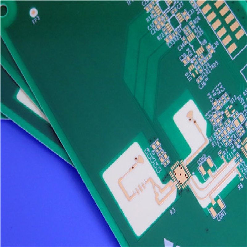
Printed Circuit Boards are custom-made products; the images and specifications provided are for reference only.
General Description
This 8-layer hybrid PCB utilizes Rogers RO4003C high-frequency PCB combined with FR-4 Tg170°C substrates, designed for demanding RF/microwave applications. 1.5mm Rogers RO4003C PCB board features a sophisticated construction with impedance-controlled routing, advanced via structures, and edge plating. With its compact 87.5mm × 40.6mm dimensions, RO4003C PCB supports complex RF circuits while maintaining excellent signal integrity. The combination of low-loss RO4003C material and reliable FR-4 substrates provides an optimal balance between high-frequency performance and cost-effective manufacturability.
PCB Construction Details
Parameter |
Specification |
Board Type |
8-layer Hybrid |
Material |
RO4003C + FR-4 Tg170°C |
Board Thickness |
1.5mm ±10% |
Board Size |
87.5mm × 40.6mm |
Min Hole Size |
0.2mm |
Min Trace Width |
115μm |
Min Spacing |
135μm |
Solder Mask |
Green, Both Sides |
Silkscreen |
White, Top Side |
Surface Finish |
ENIG |
Via Types |
Blind (L1-L2, L7-L8), Buried (L2-L7), Back Drilled (L1-L6) |
Impedance Control |
50Ω & 100Ω Differential Pairs, 50Ω Single-ended |
Via Treatment |
0.3mm Vias Filled & Capped (IPC 4761 Type VII) |
Special Feature |
Edge Plating |
Additional Components & Features
The board accommodates 41 components with 73 total pads, including 35 through-hole pads and 38 SMT pads (26 top-side, 12 bottom-side). The design incorporates 57 vias and 6 nets, supporting complex interconnections. All 0.3mm vias are filled and capped according to IPC 4761 Type VII specifications, ensuring superior reliability. The impedance-controlled design includes 50Ω and 100Ω differential pairs with precise trace/gap configurations, while back drilling from L1 to L6 minimizes signal stub effects.
Material Advantages
RO4003C laminate delivers exceptional high-frequency performance with a dielectric constant of 3.38±0.05 and low dissipation factor of 0.0027 at 10GHz. The material features excellent thermal stability (Tg >280°C) and CTE matched to copper, ensuring reliable plated through-holes. FR-4 S1000-2M substrate provides low Z-axis CTE of 2.4ppm/°C and UL 94-V0 flammability rating, complementing the high-frequency performance with robust mechanical reliability.
Typical Applications
Cellular base station antennas and power amplifiers
Automotive radar and sensor systems
RF identification tags and readers
Direct broadcast satellite LNBs
Computing and communication infrastructure
Why Choose This PCB?
This hybrid construction leverages the superior RF performance of RO4003C materials with the proven reliability and cost-effectiveness of FR-4 substrates. The advanced via structures and impedance control ensure consistent performance in demanding high-frequency applications, while standard FR-4 processing compatibility enables cost-efficient manufacturing.
Order Now for RF and Automotive Applications!
This 8-layer hybrid PCB solution delivers optimal performance for your high-frequency design requirements. Contact us today to discuss how this technology can enhance your RF and automotive electronic systems.