


 Home
-
High frequency PCB
-
Rogers 20mil 30mil 60mil AD250C PCB Antenna Material With Dielectric Constant (DK) of 2.50 and Low Loss
Home
-
High frequency PCB
-
Rogers 20mil 30mil 60mil AD250C PCB Antenna Material With Dielectric Constant (DK) of 2.50 and Low Loss
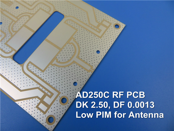
Rogers 20mil 30mil 60mil AD250C PCB Antenna Material With Dielectric Constant (DK) of 2.50 and Low Loss
Printed Circuit Boards are custom-made products; the images and specifications provided are for reference only.
Introduction
Rogers AD250C PCBs are based on polytetrafluoroethylene (PTFE), reinforced with woven fiberglass and filled with micro-dispersed ceramics. This composite structure delivers three critical performance advantages for antenna use: a controlled dielectric constant (DK) of 2.50 ±0.04, ultra-low loss (with a loss tangent of 0.0014 at 10GHz), and low passive intermodulation (PIM)—all of which make it highly suitable for antenna applications.
Among Rogers’ antenna-grade materials, AD250C stands out as a cost-effective high-frequency PCB solution for modern telecommunication infrastructure. It uniquely combines advanced composite chemistry with a build-up structure design, balancing performance and affordability for telecom use cases.
Notably, Rogers AD250C PCBs utilize low-profile copper—specifically reverse-treated electrolytic (ED) copper foil. This copper type plays a dual role: it minimizes conductive losses to preserve signal integrity, and simultaneously reduces antenna PIM, ensuring stable, interference-free operation in high-frequency telecom systems.
Typical Properties
| Electrical Properties | AD250C | Units | Test Conditions | Test Method | |
| PIM (30mil/60mil) | -159/-163 | dBc | Reflected 43 dBm swept tones at 1900 MHz, S1/S1 | Rogers Internal 50 ohm | |
| Dielectric Constant (process) | 2.52 | - | 23°C @ 50% RH | 10 GHz | IPC TM-650 2.5.5.5 (IPC TM-650 2.5.5.3) |
| Dielectric Constant (design) | 2.50 | - | C-24/23/50 | 10 GHz | Microstrip Differential Phase Length |
| Dissipation Factor (process) | 0.0013 | - | 23°C @ 50% RH | 10 GHz | IPC TM-650 2.5.5.5 |
| Thermal Coefficient of Dielectric Constant | -117 | ppm/ºC | 0°C to 100°C | 10 GHz | IPC TM-650 2.5.5.5 |
| Volume Resistivity | 4.8 x 10⁸ | Mohm-cm | C-96/35/90 | - | IPC TM-650 2.5.17.1 |
| Surface Resistivity | 4.1 x 10⁷ | Mohm | C-96/35/90 | - | IPC TM-650 2.5.17.1 |
| Electrical Strength (dielectric strength) | 979 | V/mil | - | - | IPC TM-650 2.5.6.2 |
| Dielectric Breakdown | >40 | kV | D-48/50 | X/Y direction | IPC TM-650 2.5.6 |
| Thermal Properties | |||||
| Decomposition Temperature (Td) | >500 | ˚C | 2hrs @ 105˚C | 5% Weight Loss | IPC TM-650 2.3.40 |
| Coefficient of Thermal Expansion - x | 47 | ppm/˚C | - | -55˚C to 288˚C | IPC TM-650 2.4.41 |
| Coefficient of Thermal Expansion - y | 29 | ppm/˚C | - | -55˚C to 288˚C | IPC TM-650 2.4.41 |
| Coefficient of Thermal Expansion - z | 196 | ppm/˚C | - | -55˚C to 288˚C | IPC TM-650 2.4.41 |
| Thermal Conductivity | 0.33 | W/mK | - | z direction | ASTM D5470 |
| Time to Delamination | >60 | minutes | as-received | 288˚C | IPC TM-650 2.4.24.1 |
| Mechanical Properties | |||||
| Copper Peel Strength after Thermal Stress | 2.6 (14.8) |
N/mm (lbs/in) | 10s @288˚C | 35 μm foil | IPC TM-650 2.4.8 |
| Flexural Strength (MD/CMD) | 8.8/6.4 (60.7/44.1) | MPa (ksi ) | 25°C ± 3°C | - | ASTM D790 |
| Tensile Strength (MD/CMD) | 6.0/5.6 (41.4/38.6) | MPa (ksi ) | 23°C/50% RH | - | ASTM D3039/D3039-14 |
| Flex Modulus (MD/CMD) | 885/778 (6,102/5,364) | MPa (ksi ) | 25°C ± 3°C | - | IPC-TM-650 Test Method 2.4.4 |
| Dimensional Stability (MD/CMD) | 0.02/0.06 | mils/inch | after etch + bake | - | IPC-TM-650 2.4.39a |
| Physical Properties | |||||
| Flammability | V-0 | - | - | - | UL-94 |
| Moisture Absorption | 0.04 | % | E1/105 +D48/50 | - | IPC TM-650 2.6.2.1 |
| Density | 2.28 | g/cm3 | C-24/23/50 | - | ASTM D792 |
| Specific Heat Capacity | 0.813 | J/g°K | 2 hours at 105°C | - | ASTM E2716 |
Typical Applications
1.Automotive Telematics Antenna Systems
2.Base Station Antenna Applications
3.Cellular Infrastructure Base Station Antenna
4.Commercial Satellite Radio Antenna
5.Digital Audio Broadcasting (DAB) Antennas
6.Radar Manifolds and Feed Networks
Our PCB Capability (AD250C)
| PCB Capability (AD250C) | |
| PCB Material: | PTFE based Woven Fiberglass/Ceramic Filled Composites |
| Designation: | AD250C |
| Dielectric constant: | 2.50 (10 GHz) |
| Dissipation factor | 0.0013 (10 GHz) |
| Layer count: | Double Sided PCB, Multilayer PCB, Hybrid PCB |
| Copper weight: | 1oz (35µm), 2oz (70µm) |
| Dielectric thickness | 20mil (0.508mm), 30mil (0.762mm), 60mil (1.524mm) |
| PCB size: | ≤400mm X 500mm |
| Solder mask: | Green, Black, Blue, Yellow, Red etc. |
| Surface finish: | Immersion gold (ENIG), HASL, Immersion silver, Immersion tin, OSP, ENEPIG, Bare copper, Pure gold plated etc.. |
Our advantages
-
Founded in 2003, Shenzhen Bicheng Electronics Technology Co., Ltd is an established high frequency PCB supplier and exporter in Shenzhen China, severing cellular base station antenna, satellite, high frequency passive components, microstrip line and band line circuit, millimeter wave equipment, radar systems, digital radio frequency antenna and other fields worldwide for 19 years. Our high frequency PCBs are mainly built on 3 high frequency material brands: Rogers Corporation, Taconic and Wangling. Dielectric constant ranges from 2.2 to 10.2 etc.
It includes following materials, but not limited to.
RO4350B, RO4003C, RO4730G3, RO4360G2, RO4533, RO4534, RO4535, RO4835, RO3003, RO3006, RO3010, RO3035, RO3203, RO3210;
RT/Duriod 5880; RT/Duriod 5870, RT/Duriod 6002, RT/Duroid 6010, RT/duroid 6035HTC; RT/duroid 5880LZ;
TMM3, TMM4, TMM6, TMM10, TMM10i, TMM13i, Kappa 438;
TLF-35; RF-35TC, RF-60A, RF-60TC, RF-35A2, RF-45, RF-10, TRF-45; TLX-0, TLX-6, TLX-7, TLX-8; TLX-9, TLY-3, TLY-5, TLY-5Z;
F4B (DK2.2 DK2.65 DK2.85 DK2.94, DK3.0, DK3.2, DK3.38, DK3.5, DK4.0, DK4.4, DK6.15, DK10.2);
AD250C, AD255C, AD300D, AD350A, AD450, AD600, AD1000, TC350; TC600;
DiClad 880, DiClad 870, DiClad 527, IsoClad 917
Nelco N4000, N9350, N9240;