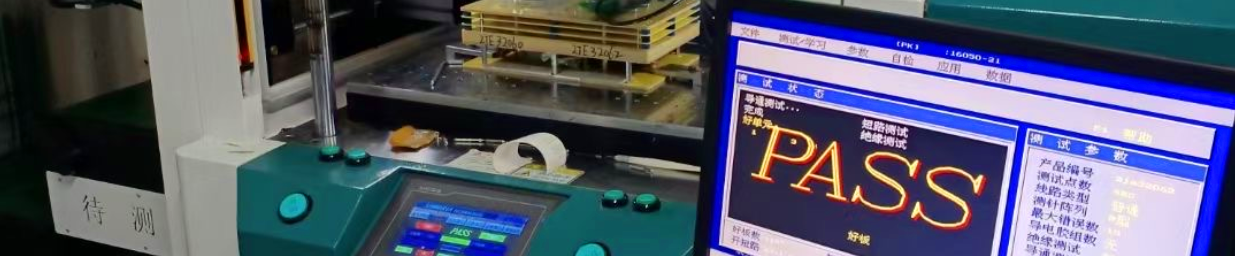
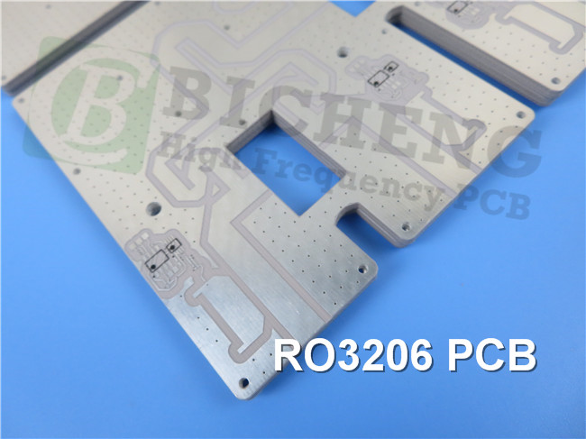
Rogers RO3206 High Frequency PCB Material Introduction Hi Greetings. Welcome back to our channel. I am Ivy, the regional sales manger for Bicheng PCB. Today we’ll discuss Rogers RO3206 high frequency circuits which are ceramic-filled laminates reinforced with woven fiberglass. Rogers RO3206 high-frequency circuit materials are engineered to offer exceptional electrical performance and mechanical stability at competitive prices. Rogers RO3206 PCB materials have one distinguishing characteristic - improved mechanical stability. RO3206 laminate PCBs combine the surface smoothness of a non-woven PTFE laminate, for finer line etching tolerances, with the rigidity of a woven-glass PTFE laminate. These materials can be fabricated into printed circuit boards using standard PTFE circuit board processing techniques. RO3206 laminates are manufactured under an ISO 9002 certified quality system. Let's take a closer look at its properties. Rogers RO3206 Typical Properties The dielectric constant is an important property of this material. At a frequency of 10 GHz and a temperature of 23°C, the process dielectric constant of RO3206 laminate is 6.15 ± 0.15 in the Z direction, as measured by the IPC-TM-650 2.5.5.5 Clamped Stripline test method. For design purposes at frequencies between 8 GHz and 40 GHz, the dielectric constant in the Z direction of RO3206 laminate PCB is 6.6 and is measured using the Differential Phase Length Method. The dissipation factor is another important property. At a frequency of 10 GHz and a temperature of 23°C, the Df value is 0.0027 in the Z direction, as measured by the IPC-TM-650 2.5.5.5 test method. The thermal coefficient of εr is -212 ppm/°C in the Z direction, as measured at a frequency of 10 GHz and a temperature range of 0-100°C using the IPC-TM-650 2.5.5.5 test method. Dimensional stability is another important property of this material. In the X and Y directions, the dimensional stability is 0.8 mm/m when measured using COND A of the ASTM D257 test method. Rogers RO3206 laminate also has good electrical properties. The volume resistivity is 10^3 MΩ?cm and the surface resistivity is 10^3 MΩ, both measured using COND A of the IPC 2.5.17.1 test method. RO3206 circuit board has a tensile modulus of 462 kpsi in both the MD and CMD directions, as measured at 23°C using the ASTM D638 test method. Water absorption is less than 0.1% when tested using D24/23 of the IPC-TM-650 2.6.2.1 test method. The specific heat of the RO3206 PCB is 0.85 J/g/K, calculated based on its chemical composition. The coefficient of thermal expansion is 13, 13 and 34 ppm/°C in the X, Y, and Z directions, measured at a temperature of 23°C and 50% relative humidity using the IPC-TM-650 2.4.41 test method. The Td, or thermal decomposition temperature, is 500°C when measured using the TGA test method according to ASTM D3850. The material has a density of 2.7 g/cm3 and is tan in color. The copper peel strength of the RO3206 is 10.7 pli when tested using 1 oz. ED copper after solder float, as measured by the IPC-TM-2.4.8 test method. RO3206 PCB material is also lead-free process compatible, and has a V-0 flammability rating according to UL 94. Property RO3206 Direction Unit Condtion Test Method Dielectric Constant, εr Process 6.15± 0.15 Z - 10 GHz 23°C IPC-TM-650 2.5.5.5 Clamped Stripline Dielectric Constant, εr Design 6.6 Z - 8 ?GHz - 40 GHz Differential Phase Length Method Dissipation Factor, tan δ 0.0027 Z - 10 GHz 23°C IPC-TM-650 2.5.5.5 Thermal Coefficient of εr -212 Z ppm/°C 10 GHz 0-100°C IPC-TM-650 2.5.5.5 Dimensional Stability 0.8 X,Y mm/m COND A ASTM D257 Volume Resistivity 10^3 MΩ•cm COND A IPC 2.5.17.1 Surface Resistivity 10^3 MΩ COND A IPC 2.5.17.1 Tensile Modulus 462 MD kpsi 23°C ASTM D638 Water Absorption <0.1 - % D24/23 IPC-TM-650 Specific Heat 0.85 J/g/K Calculated Thermal Conductivity 0.67 - W/m/K 80°C ASTM C518 Coefficient of Thermal Expansion (-55 to 288 °C) 13 X,Y, ppm/°C 23°C/50% RH IPC-TM-650 2.4.41 Td 500 °C TGA ASTM D3850 Color Tan Density 2.7 gm/cm3 Copper Peel Strength 10.7 pli 1 oz. EDC After Solder Float IPC-TM-2.4.8 Flammability V-0 UL 94 Lead Free Process YES RO3206 PCB Capability We offer a variety of PCB options for Rogers RO3206, including single-sided, double-sided, multilayer, and hybrid boards. Copper weights of 1oz (35μm) and 2oz (70μm) are available, as well as dielectric thicknesses of 25mil (0.635mm) and 50mil (1.27mm). Rogers RO3206 PCB Boards can be up to 400mm x 500mm in size, either as a single board or multiple types in a panel. Solder mask options include green, black, blue, yellow, and red. Our surface finish options include immersion gold, HASL, immersion silver, immersion tin, ENEPIG, OSP, bare copper, and pure gold plated finishes, all of which are designed to optimize performance and reliability. PCB Material: Ceramic-filled Laminates Reinforced with Woven Fiberglass Designation: RO3206 Dielectric constant: 6.15 Dissipation factor 0.0027 Layer count: Single Sided, Double Sided, Multi-layer PCB, Hybrid PCB Copper weight: 1oz (35µm), 2oz (70µm) Dielectric thickness 25mil (0.635mm), 50mil (1.27mm) PCB size: ≤400mm X 500mm Solder mask: Green, Black, Blue, Yellow, Red etc. Surface finish: Immersion gold, HASL, Immersion silver, Immersion tin, ENEPIG, OSP, Bare copper, Pure gold plated etc.. A piece of RO3206 PCB The screen showcases a 50mil RO3206 PCB featuring immersion gold, meticulously crafted for microstrip patch antennas. RO3206 rigid PCBs have a wide range of typical applications encompassing automotive collision avoidance systems, automotive GPS antennas, wireless telecommunications systems, direct broadcast satellites, cable datalink systems, remote meter readers, power backplanes, LMDS and wireless broadband, as well as base station infrastructure. Conclusion RO3206 PCB substrates are compatible with traditional electroless copper and direct deposit metallization processes. Cores should be baked (30-90 minutes @ 110°C-125°C) prior to metal deposition unless plasma treatment has been used to prepare the hole walls for plating. Standard equipment and chemical processes are used to plate, image, and etch circuit patterns onto RO32006 materials. It is important to handle these processes with care to maintain the integrity of the post-etch laminate surface. The topography that remains after copper removal promotes improved adhesion to solder masks. Well this concludes today's episode. Thank you for reading. See you next time.
462
CMD
2.6.2.1
34
Z
Compatible


 Home
Home