

 Home
-
HDI PCB
-
8-Layer HDI PCB Built On Tg175°C FR-4 Immersion Gold PCB for Satellite Radio Applications
Home
-
HDI PCB
-
8-Layer HDI PCB Built On Tg175°C FR-4 Immersion Gold PCB for Satellite Radio Applications
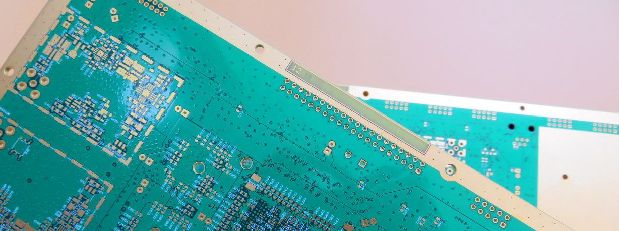
8-Layer HDI PCB Built On Tg175°C FR-4 Immersion Gold PCB for Satellite Radio Applications
Printed Circuit Boards are custom-made products; the images and specifications provided are for reference only.
1.1 General description
This 8-layer HDI printed circuit board is engineered for high-frequency applications such as satellite radio systems, constructed on high-performance FR-4 Tg175℃ substrate from ITEQ Taiwan. With a 1.6mm thickness and advanced HDI structures—including blind vias from top layer to inner 2 and buried vias from inner 2 to inner 4—it ensures reliable signal integrity and interconnection density. Featuring immersion gold surface finish on pads, Taiyo green solder mask, and white silkscreen, each 1-up panel is manufactured to IPC 6012 Class 2 standards using supplied Gerber data and shipped in batches of 25 panels, providing an ideal solution for demanding RF and telecommunications designs.
1.2 Features and benefits
1. High Tg Materials are RoHS compliant and suitable for high thermal reliability needs;
2. Immersin gold has high solderability, no stressing of circuit boards and less contamination of PCB surface;
3. Delivery on time. Higher than 98% on-time-delivery rate;
4. 30000㎡ output capability per month;
5. More than 18 years of experience;
6. Powerful PCB capabilities support your research and development, sales and marketing;
7. Any Layer HDI PCBs;
8. International approvals;
.jpg)
Appendix: Data sheet of DiClad 870
| PCB SIZE | 215 x 212mm=1PCS | |||
| BOARD TYPE | Multilayer PCB | |||
| Number of Layers | 8 layers | |||
| Surface Mount Components | YES | |||
| Through Hole Components | YES | |||
| LAYER STACKUP | copper ------- 18um(0.5oz)+plate TOP layer | |||
| Prepreg 7628(43%) 0.195mm | ||||
| copper ------- 35um(1oz) MidLayer 1 | ||||
| FR-4 0.2mm | ||||
| copper ------- 35um(1oz) MidLayer 2 | ||||
| Prepreg 7628(43%) 0.195mm | ||||
| copper ------- 35um(1oz) MidLayer 3 | ||||
| FR-4 0.2mm | ||||
| copper ------- 35um(1oz) MidLayer 4 | ||||
| Prepreg 7628(43%) 0.195mm | ||||
| copper ------- 35um(1oz) MidLayer 5 | ||||
| FR-4 0.2mm | ||||
| copper ------- 35um(1oz) MidLayer 6 | ||||
| Prepreg 7628(43%) 0.195mm | ||||
| copper ------- 18um(0.5oz)+plate BOT Layer | ||||
| TECHNOLOGY | ||||
| Minimum Trace and Space: | 4mil/4mil | |||
| Minimum / Maximum Holes: | 0.3/3.2mm | |||
| Number of Different Holes: | 18 | |||
| Number of Drill Holes: | 11584 | |||
| Number of Milled Slots: | 2 | |||
| Number of Internal Cutouts: | 0 | |||
| Impedance Control: | no | |||
| Number of Gold finger: | 0 | |||
| BOARD MATERIAL | ||||
| Glass Epoxy: | FR-4 TG170℃, er<5.4.IT-180, ITEQ Supplied | |||
| Final foil external: | 1oz | |||
| Final foil internal: | 1oz | |||
| Final height of PCB: | 1.6mm ±0.16 | |||
| PLATING AND COATING | ||||
| Surface Finish | Immersion gold (32.1% ) 0.05µm over 3µm nickel | |||
| Solder Mask Apply To: | TOP and Bottom, 12micron Minimum | |||
| Solder Mask Color: | Green, PSR-2000 KX700G, Taiyo Supplied. | |||
| Solder Mask Type: | LPSM | |||
| CONTOUR/CUTTING | Routing, stamp holes. | |||
| MARKING | ||||
| Side of Component Legend | TOP and Bottom. | |||
| Colour of Component Legend | White, S-380W, Taiyo Supplied. | |||
| Manufacturer Name or Logo: | Marked on the board in a conductor and leged FREE AREA | |||
| VIA | plated through hole(PTH), minimum size 0.3mm. | |||
| FLAMIBILITY RATING | UL 94-V0 Approval MIN. | |||
| DIMENSION TOLERANCE | ||||
| Outline dimension: | 0.0059"" | |||
| Board plating: | 0.0029"" | |||
| Drill tolerance: | 0.002"" | |||
| TEST | 100% Electrical Test prior shipment | |||
| TYPE OF ARTWORK TO BE SUPPLIED | email file, Gerber RS-274-X, PCBDOC etc | |||
| SERVICE AREA | Worldwide, Globally. |