

 Home
-
F4B PCB
-
F4BTMS High-Frequency PCB: Enhanced Ceramic Composite Laminates for High-Performance Applications
Home
-
F4B PCB
-
F4BTMS High-Frequency PCB: Enhanced Ceramic Composite Laminates for High-Performance Applications
F4BTMS High-Frequency PCB: Enhanced Ceramic Composite Laminates for High-Performance Applications
Printed Circuit Boards are custom-made products; the images and specifications provided are for reference only.
Introduction
The F4BTMS High-Frequency PCB is an upgraded version of the F4BTM series. Based on the foundation of the F4BTM series, it has achieved significant technological breakthroughs in material formulation and manufacturing processes. This material incorporates a large amount of ceramic components and uses ultra-thin and ultra-fine fiberglass cloth for reinforcement, resulting in significantly improved performance and a wider range of dielectric constants. It is a high-reliability material suitable for aerospace applications and can replace similar foreign products.
By incorporating a small amount of ultra-thin and ultra-fine fiberglass cloth for reinforcement, and simultaneously achieving a large-scale and uniform mixture of special nano-ceramics and polytetrafluoroethylene (PTFE) resin, the F4BTMS High-Frequency PCB can minimize the fiberglass effect during electromagnetic wave propagation, reduce dielectric loss, and enhance dimensional stability. This material has reduced anisotropy in the X/Y/Z directions, enabling it to adapt to higher-frequency application scenarios, with enhanced electrical strength and improved thermal conductivity. It also possesses excellent low coefficient of thermal expansion and stable dielectric temperature characteristics.
The F4BTMS series comes standard with RTF (Reverse Treat Foil) low-roughness copper foil, which not only reduces conductor loss but also offers excellent peel strength. It can be paired with copper-based or aluminum-based options. Among them, the F4BTMS294 model can be combined with embedded 50Ω resistor copper foil to produce resistor film substrates.
Leveraging the material's outstanding mechanical and physical properties, the F4BTMS High-Frequency PCB can be processed using standard PTFE board manufacturing techniques. It is suitable for the processing of multi-layer, high-layer-count, and backplane PCBs, and also demonstrates excellent processability in terms of dense holes and fine-line routing.
Product Features
- Minimal dielectric constant tolerance and excellent batch-to-batch consistency.
- Extremely low dielectric loss.
- Stable dielectric constant and low loss within frequencies up to 40GHz, meeting the requirements of phase-sensitive applications.
- Excellent temperature coefficient of dielectric constant and dielectric loss, maintaining frequency and phase stability between -55°C and 150°C.
- Excellent resistance to radiation, retaining stable dielectric and physical properties even after exposure to irradiation.
- Low outgassing performance, meeting the vacuum outgassing requirements for aerospace applications.
- Minimal thermal expansion coefficients in the X/Y/Z directions, ensuring dimensional stability and reliable hole copper connections.
- Improved thermal conductivity, suitable for high-power applications.
- Excellent dimensional stability.
- Low water absorption.
Models & Data Sheet
| Product Technical Parameters | Product Models & Data Sheet | ||||||||||||
| Product Features | Test Conditions | Unit | F4BTMS220 | F4BTMS233 | F4BTMS255 | F4BTMS265 | F4BTMS294 | F4BTMS300 | F4BTMS350 | F4BTMS430 | F4BTMS450 | F4BTMS615 | F4BTMS1000 |
| Dielectric Constant (Typical) | 10GHz | / | 2.2 | 2.33 | 2.55 | 2.65 | 2.94 | 3.00 | 3.50 | 4.30 | 4.50 | 6.15 | 10.20 |
| Dielectric Constant Tolerance | / | / | ±0.02 | ±0.03 | ±0.04 | ±0.04 | ±0.04 | ±0.04 | ±0.05 | ±0.09 | ±0.09 | ±0.12 | ±0.2 |
| Dielectric Constant (Design) | 10GHz | / | 2.2 | 2.33 | 2.55 | 2.65 | 2.94 | 3.0 | 3.50 | 4.3 | 4.5 | 6.15 | 10.2 |
| Loss Tangent (Typical) | 10GHz | / | 0.0009 | 0.0010 | 0.0012 | 0.0012 | 0.0012 | 0.0013 | 0.0016 | 0.0015 | 0.0015 | 0.0020 | 0.0020 |
| 20GHz | / | 0.0010 | 0.0011 | 0.0013 | 0.0014 | 0.0014 | 0.0015 | 0.0019 | 0.0019 | 0.0019 | 0.0023 | 0.0023 | |
| 40GHz | / | 0.0013 | 0.0015 | 0.0016 | 0.0018 | 0.0018 | 0.0019 | 0.0024 | 0.0024 | 0.0024 | / | / | |
| Dielectric Constant Temperature Coefficient | -55 º~150ºC | PPM/℃ | -130 | -122 | -92 | -88 | -20 | -20 | -39 | -60 | -58 | -96 | -320 |
| Peel Strength | 1 OZ RTF copper | N/mm | >2.4 | >2.4 | >1.8 | >1.8 | >1.2 | >1.2 | >1.2 | >1.2 | >1.2 | >1.2 | >1.2 |
| Volume Resistivity | Standard Condition | MΩ.cm | ≥1×10^8 | ≥1×10^8 | ≥1×10^8 | ≥1×10^8 | ≥1×10^8 | ≥1×10^8 | ≥1×10^8 | ≥1×10^8 | ≥1×10^8 | ≥1×10^8 | ≥1×10^8 |
| Surface Resistivity | Standard Condition | MΩ | ≥1×10^8 | ≥1×10^8 | ≥1×10^8 | ≥1×10^8 | ≥1×10^8 | ≥1×10^8 | ≥1×10^8 | ≥1×10^8 | ≥1×10^8 | ≥1×10^8 | ≥1×10^8 |
| Electrical Strength (Z direction) | 5KW,500V/s | KV/mm | >26 | >30 | >32 | >34 | >40 | >40 | >42 | >44 | >45 | >48 | >23 |
| Breakdown Voltage (XY direction) | 5KW,500V/s | KV | >35 | >38 | >40 | >42 | >48 | >52 | >55 | >52 | >54 | >55 | >42 |
| Coefficientof Thermal Expansion (X, Y direction) | -55 º~288ºC | ppm/ºC | 40, 50 | 35, 40 | 15, 20 | 15, 20 | 10, 12 | 10, 11 | 10, 12 | 13, 12 | 12, 12 | 10, 12 | 16, 18 |
| Coefficientof Thermal Expansion (Z direction) | -55 º~288ºC | ppm/ºC | 290 | 220 | 80 | 72 | 22 | 22 | 20 | 47 | 45 | 40 | 32 |
| Thermal Stress | 260℃, 10s,3 times | / | No delamination | No delamination | No delamination | No delamination | No delamination | No delamination | No delamination | No delamination | No delamination | No delamination | No delamination |
| Water Absorption | 20±2℃, 24 hours | % | 0.02 | 0.02 | 0.025 | 0.025 | 0.02 | 0.025 | 0.03 | 0.08 | 0.08 | 0.1 | 0.03 |
| Density | Room Temperature | g/cm3 | 2.18 | 2.22 | 2.26 | 2.26 | 2.25 | 2.28 | 2.3 | 2.51 | 2.53 | 2.75 | 3.2 |
| Long-Term Operating Temperature | High-Low Temperature Chamber | ℃ | -55~+260 | -55~+260 | -55~+260 | -55~+260 | -55~+260 | -55~+260 | -55~+260 | -55~+260 | -55~+260 | -55~+260 | -55~+260 |
| Thermal Conductivity | Z direction | W/(M.K) | 0.26 | 0.28 | 0.31 | 0.36 | 0.58 | 0.58 | 0.6 | 0.63 | 0.64 | 0.67 | 0.81 |
| Flammability | / | UL-94 | V-0 | V-0 | V-0 | V-0 | V-0 | V-0 | V-0 | V-0 | V-0 | V-0 | V-0 |
| Material Composition | / | / | PTFE,Ultra-thin and ultra-fine (quartz) fiberglass. | PTFE,Ultra-thin and ultra-fine fiberglass, ceramics. | |||||||||
Our PCB Capability (F4BTMS)
| PCB Capability (F4BTMS) | |||
| PCB Material: | PTFE,Ultra-thin and ultra-fine fiberglass, ceramics. | ||
| Designation (F4BTMS ) | F4BTMS | DK (10GHz) | DF (10 GHz) |
| F4BTMS220 | 2.2±0.02 | 0.0009 | |
| F4BTMS233 | 2.33±0.03 | 0.0010 | |
| F4BTMS255 | 2.55±0.04 | 0.0012 | |
| F4BTMS265 | 2.65±0.04 | 0.0012 | |
| F4BTMS294 | 2.94±0.04 | 0.0012 | |
| F4BTMS300 | 3.0±0.04 | 0.0013 | |
| F4BTMS350 | 3.5±0.05 | 0.0016 | |
| F4BTMS430 | 4.3±0.09 | 0.0015 | |
| F4BTMS450 | 4.5±0.09 | 0.0015 | |
| F4BTMS615 | 6.15±0.12 | 0.0020 | |
| F4BTMS1000 | 10.2±0.2 | 0.0020 | |
| Layer count: | Single Sided, Double Sided PCB, Multilayer PCB, Hybrid PCB | ||
| Copper weight: | 0.5oz (17 µm), 1oz (35µm), 2oz (70µm) | ||
| Dielectric thickness | 0.09mm (3.5mil), 0.127mm (5mil), 0.254mm(10mil),0.508mm(20mil), 0.635mm(25mil), 0.762mm(30mil), 0.787mm(31mil), 1.016mm(40mil), 1.27mm(50mil), 1.5mm(59mil), 1.524mm(60mil), 1.575mm(62mil), 2.03mm(80mil), 2.54mm(100mil), 3.175mm(125mil), 4.6mm(160mil), 5.08mm(200mil), 6.35mm(250mil) | ||
| PCB size: | ≤400mm X 500mm | ||
| Solder mask: | Green, Black, Blue, Yellow, Red etc. | ||
| Surface finish: | Bare copper, HASL, ENIG, Immersion silver, Immersion tin, OSP, Pure gold, ENEPIG etc.. |
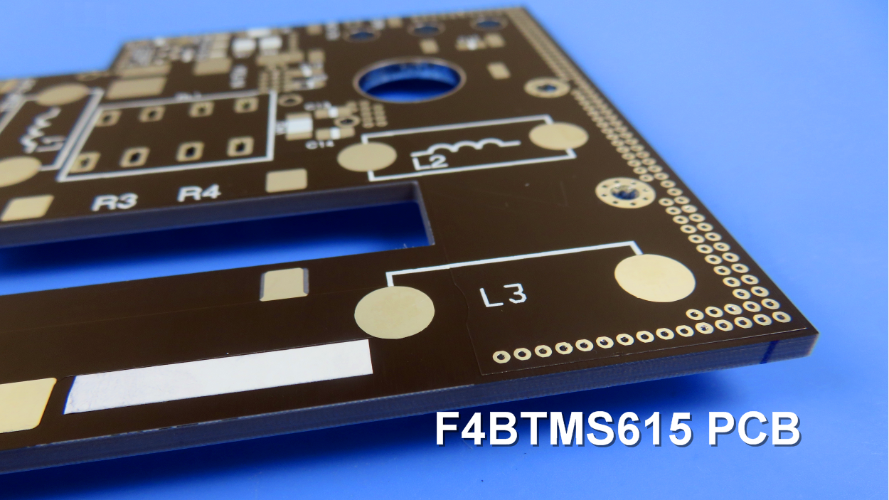
A F4BTMS PCB and Typical Applications:
Presented on the screen is an F4BTMS high-frequency PCB, utilizing a 3.2mm substrate with HASL coating on the pads. F4BTMS PCBs are extensively employed in various domains, including:
- Aerospace and aviation equipment, space installations, and cabin setups.
- Microwave and RF applications.
- Radar systems, particularly in military applications.
- Feed networks for signal distribution.
- Phase-sensitive antennas and phased array antennas.
- Satellite communications, and much more.
Final (F4BTMS series aluminum-based/copper-based boards)
The laminates of the F4BTMS series are available in aluminum-based or copper-based material options. Their structure features a dielectric layer with one side coated in copper foil and the other side covered with an aluminum-based or copper-based layer—this specific configuration functions to provide both shielding and heat dissipation capabilities.
The model numbers are F4BTMS***-AL or F4BTMS***-CU. For example,
F4BTMS220-AL represents F4BTMS220 with aluminum-based substrate.
F4BTMS294-CU represents F4BTMS294 with copper-based substrate.