

 Home
-
F4B PCB
-
F4BTM High Frequency PCB Advanced Low Thermal Expansion Coefficient Materials for High-Performance Circuitry
Home
-
F4B PCB
-
F4BTM High Frequency PCB Advanced Low Thermal Expansion Coefficient Materials for High-Performance Circuitry
F4BTM High Frequency PCB Advanced Low Thermal Expansion Coefficient Materials for High-Performance Circuitry
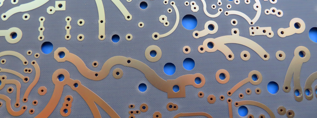
Printed Circuit Boards are custom-made products; the images and specifications provided are for reference only.
Introduction
Discover F4BTM series PCB, meticulously crafted by combining fiberglass cloth, nano-ceramic particles, and polytetrafluoroethylene (PTFE) resin under strict manufacturing controls. The core F4BM dielectric is innovatively modified with nano-ceramics, resulting in a material that offers a higher dielectric constant, superior thermal performance, excellent dimensional stability, and high insulation resistance, plus improved thermal conductivity—without compromising on low signal loss.
Choose the perfect laminate for your design needs: F4BTM with standard ED copper foil is ideal for general applications without strict PIM requirements. For superior performance in critical applications like 5G infrastructure, the F4BTME version features reverse-treated copper foil (RTF). This ensures outstanding Passive Intermodulation (PIM) characteristics, enables more precise control over circuit lines, and minimizes conductor loss for enhanced signal integrity.
Features & Benefits
- DK range from 2.98 to 3.5 is available
- Addition of ceramics enhances the performance.
- F4BTME exhibits excellent PIM performance,
- Comes in various thicknesses and sizes, offers cost savings
- Commercialization, large-scale production, and high cost-effectiveness.
- Radiation-resistant and low out-gassing properties
Models & Data Sheet
| Product Technical Parameters | Product Models & Data Sheet | ||||||
| Product Features | Test Conditions | Unit | F4BTM298 | F4BTM300 | F4BTM320 | F4BTM350 | |
| Dielectric Constant (Typical) | 10GHz | / | 2.98 | 3.0 | 3.2 | 3.5 | |
| Dielectric Constant Tolerance | / | / | ±0.06 | ±0.06 | ±0.06 | ±0.07 | |
| Loss Tangent (Typical) | 10GHz | / | 0.0018 | 0.0018 | 0.0020 | 0.0025 | |
| 20GHz | / | 0.0023 | 0.0023 | 0.0026 | 0.0035 | ||
| Dielectric Constant Temperature Coefficient | -55 º~150ºC | PPM/℃ | -78 | -75 | -75 | -60 | |
| Peel Strength | 1 OZ F4BTM | N/mm | >1.6 | >1.6 | >1.6 | >1.6 | |
| 1 OZ F4BTME | N/mm | >1.4 | >1.4 | >1.4 | >1.4 | ||
| Volume Resistivity | Standard Condition | MΩ.cm | ≥1×10^7 | ≥1×10^7 | ≥1×10^7 | ≥1×10^7 | |
| Surface Resistivity | Standard Condition | MΩ | ≥1×10^6 | ≥1×10^6 | ≥1×10^6 | ≥1×10^6 | |
| Electrical Strength (Z direction) | 5KW,500V/s | KV/mm | >26 | >30 | >32 | >32 | |
| Breakdown Voltage (XY direction) | 5KW,500V/s | KV | >34 | >35 | >40 | >40 | |
| Coefficientof Thermal Expansion | XY direction | -55 º~288ºC | ppm/ºC | 15,16 | 15,16 | 13,15 | 10,12 |
| Z direction | -55 º~288ºC | ppm/ºC | 78 | 72 | 58 | 51 | |
| Thermal Stress | 260℃, 10s,3 times | No delamination | No delamination | No delamination | No delamination | ||
| Water Absorption | 20±2℃, 24 hours | % | ≤0.05 | ≤0.05 | ≤0.05 | ≤0.05 | |
| Density | Room Temperature | g/cm3 | 2.25 | 2.25 | 2.20 | 2.20 | |
| Long-Term Operating Temperature | High-Low Temperature Chamber | ℃ | -55~+260 | -55~+260 | -55~+260 | -55~+260 | |
| Thermal Conductivity | Z direction | W/(M.K) | 0.42 | 0.42 | 0.50 | 0.54 | |
| PIM | Only applicable to F4BTME | dBc | ≤-160 | ≤-160 | ≤-160 | ≤-160 | |
| Flammability | / | UL-94 | V-0 | V-0 | V-0 | V-0 | |
| Material Composition | / | / | PTFE, Fiberglass Cloth, nano-ceramics F4BTM paired with ED copper foil, F4BTME paired with reverse-treated (RTF) copper foil. |
||||
Our PCB Capability (F4BTM)
| PCB Capability (F4BTM) | |||
| PCB Material: | PTFE / glass fiber cloth / Nano-ceramic filler | ||
| Designation (F4BTM ) | F4BTM | DK (10GHz) | DF (10 GHz) |
| F4BTM298 | 2.98±0.06 | 0.0018 | |
| F4BTM300 | 3.0±0.06 | 0.0018 | |
| F4BTM320 | 3.2±0.06 | 0.0020 | |
| F4BTM350 | 3.5±0.07 | 0.0025 | |
| Layer count: | Single Sided, Double Sided PCB, Multilayer PCB, Hybrid PCB | ||
| Copper weight: | 0.5oz (17 µm), 1oz (35µm), 2oz (70µm) | ||
| Dielectric thickness (or overall thickness) | 0.25mm, 0.508mm, 0.762mm, 0.8mm, 1.0mm, 1.016mm, 1.27mm, 1.524mm, 2.0mm, 3.0mm, 4.0mm, 5.0mm, 6.0mm, 8.0mm, 10.0mm, 12.0mm | ||
| PCB size: | ≤400mm X 500mm | ||
| Solder mask: | Green, Black, Blue, Yellow, Red etc. | ||
| Surface finish: | Bare copper, HASL, ENIG, Immersion silver, Immersion tin, OSP, Pure gold, ENEPIG etc.. |