

 Home
Home
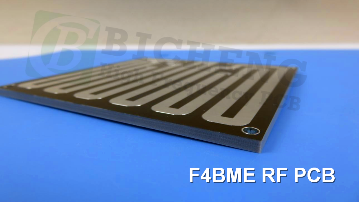
F4BME Low-Loss PTFE PCB Laminates with Controlled DK and PIM Performance
Printed Circuit Boards are custom-made products; the images and specifications provided are for reference only.
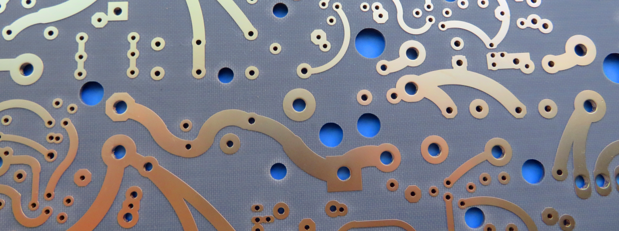
The F4BM series PCB represents a technologically advanced category of high-frequency PCB laminates, manufactured through a precisely controlled process that combines fiberglass cloth with polytetrafluoroethylene (PTFE) resin and film. This sophisticated formulation delivers significantly enhanced electrical performance over standard F4B materials, featuring a wider selection of dielectric constants (Dk), reduced dielectric loss (Df), superior insulation resistance, and exceptional operational stability. These materials provide a dependable domestic alternative to comparable international products.
The product line offers specialized copper foil configurations to address different application requirements. The standard F4BM variant utilizes Electro-Deposited (ED) copper foil, delivering cost-efficient performance for systems without stringent Passive Intermodulation (PIM) specifications. For demanding RF applications, the F4BME version incorporates Reverse-Treated Foil (RTF) copper, delivering superior low-PIM characteristics, enhanced precision in circuit patterning, and reduced conductor loss.
Through precise manipulation of the PTFE-to-fiberglass ratio, both F4BM and F4BME laminates achieve exacting control over dielectric properties while preserving low-loss characteristics and mechanical stability. Increasing the fiberglass content elevates the dielectric constant while simultaneously improving dimensional stability, reducing the coefficient of thermal expansion (CTE), and enhancing thermal drift performance, though with a minimal trade-off in dielectric loss parameters.
Features & Benefits
-DK options available: 2.17 to 3.0, customizable DK
-Low loss
-F4BME paired with RTF copper foil, excellent PIM performance
-Diverse sizes, cost-effective
-Radiation resistance, low outgassing
-Commercialized, large-scale production, high cost-effectiveness
Laminate Models and Data Sheet
| Product Technical Parameters | Product Model & Data Sheet | |||||||||||
| Product Features | Test Conditions | Unit | F4BME217 | F4BME220 | F4BME233 | F4BME245 | F4BME255 | F4BME265 | F4BME275 | F4BME294 | F4BME300 | |
| Dielectric Constant (Typical) | 10GHz | / | 2.17 | 2.2 | 2.33 | 2.45 | 2.55 | 2.65 | 2.75 | 2.94 | 3.0 | |
| Dielectric Constant Tolerance | / | / | ±0.04 | ±0.04 | ±0.04 | ±0.05 | ±0.05 | ±0.05 | ±0.05 | ±0.06 | ±0.06 | |
| Loss Tangent (Typical) | 10GHz | / | 0.001 | 0.001 | 0.0011 | 0.0012 | 0.0013 | 0.0013 | 0.0015 | 0.0016 | 0.0017 | |
| 20GHz | / | 0.0014 | 0.0014 | 0.0015 | 0.0017 | 0.0018 | 0.0019 | 0.0021 | 0.0023 | 0.0025 | ||
| Dielectric Constant Temperature Coefficient | -55ºC~150ºC | PPM/℃ | -150 | -142 | -130 | -120 | -110 | -100 | -92 | -85 | -80 | |
| Peel Strength | 1 OZ F4BM | N/mm | >1.8 | >1.8 | >1.8 | >1.8 | >1.8 | >1.8 | >1.8 | >1.8 | >1.8 | |
| 1 OZ F4BME | N/mm | >1.6 | >1.6 | >1.6 | >1.6 | >1.6 | >1.6 | >1.6 | >1.6 | >1.6 | ||
| Volume Resistivity | Standard Condition | MΩ.cm | ≥6×10^6 | ≥6×10^6 | ≥6×10^6 | ≥6×10^6 | ≥6×10^6 | ≥6×10^6 | ≥6×10^6 | ≥6×10^6 | ≥6×10^6 | |
| Surface Resistivity | Standard Condition | MΩ | ≥1×10^6 | ≥1×10^6 | ≥1×10^6 | ≥1×10^6 | ≥1×10^6 | ≥1×10^6 | ≥1×10^6 | ≥1×10^6 | ≥1×10^6 | |
| Electrical Strength (Z direction) | 5KW,500V/s | KV/mm | >23 | >23 | >23 | >25 | >25 | >25 | >28 | >30 | >30 | |
| Breakdown Voltage (XY direction) | 5KW,500V/s | KV | >30 | >30 | >32 | >32 | >34 | >34 | >35 | >36 | >36 | |
| Coefficientof Thermal Expansion | XY direction | -55 º~288ºC | ppm/ºC | 25, 34 | 25, 34 | 22, 30 | 20, 25 | 16, 21 | 14, 17 | 14, 16 | 12, 15 | 12, 15 |
| Z direction | -55 º~288ºC | ppm/ºC | 240 | 240 | 205 | 187 | 173 | 142 | 112 | 98 | 95 | |
| Thermal Stress | 260℃, 10s,3 times | No delamination | No delamination | No delamination | No delamination | No delamination | No delamination | No delamination | No delamination | No delamination | ||
| Water Absorption | 20±2℃, 24 hours | % | ≤0.08 | ≤0.08 | ≤0.08 | ≤0.08 | ≤0.08 | ≤0.08 | ≤0.08 | ≤0.08 | ≤0.08 | |
| Density | Room Temperature | g/cm3 | 2.17 | 2.18 | 2.20 | 2.22 | 2.25 | 2.25 | 2.28 | 2.29 | 2.29 | |
| Long-Term Operating Temperature | High-Low Temperature Chamber | ℃ | -55~+260 | -55~+260 | -55~+260 | -55~+260 | -55~+260 | -55~+260 | -55~+260 | -55~+260 | -55~+260 | |
| Thermal Conductivity | Z direction | W/(M.K) | 0.24 | 0.24 | 0.28 | 0.30 | 0.33 | 0.36 | 0.38 | 0.41 | 0.42 | |
| PIM | Only applicable to F4BME | dBc | ≤-159 | ≤-159 | ≤-159 | ≤-159 | ≤-159 | ≤-159 | ≤-159 | ≤-159 | ≤-159 | |
| Flammability | / | UL-94 | V-0 | V-0 | V-0 | V-0 | V-0 | V-0 | V-0 | V-0 | V-0 | |
| Material Composition | / | / | PTFE, Fiberglass Cloth F4BM paired with ED copper foil, F4BME paired with reverse-treated (RTF) copper foil. |
|||||||||
Our PCB Capability (F4BME )
| PCB Capability (F4BME) | |||
| PCB Material: | PTFE glass fiber cloth copper clad laminates | ||
| Designation (F4BME ) | F4BME | DK (10GHz) | DF (10 GHz) |
| F4BME217 | 2.17±0.04 | 0.0010 | |
| F4BME220 | 2.20±0.04 | 0.0010 | |
| F4BME233 | 2.33±0.04 | 0.0011 | |
| F4BME245 | 2.45±0.05 | 0.0012 | |
| F4BME255 | 2.55±0.05 | 0.0013 | |
| F4BME265 | 2.65±0.05 | 0.0013 | |
| F4BME275 | 2.75±0.05 | 0.0015 | |
| F4BME294 | 2.94±0.06 | 0.0016 | |
| F4BME300 | 3.00±0.06 | 0.0017 | |
| Layer count: | Single Sided, Double Sided PCB, Multilayer PCB, Hybrid PCB | ||
| Copper weight: | 0.5oz (17 µm), 1oz (35µm), 2oz (70µm) | ||
| Dielectric thickness (or overall thickness) | 0.127mm (dielectric), 0.2mm, 0.25mm, 0.5mm, 0.508mm, 0.762mm, 0.8mm, 1.0mm, 1.5mm, 1.524mm, 1.575mm, 2.0mm, 2.5mm, 3.0mm, 4.0mm, 5.0mm, 6.0mm, 8.0mm, 10.0mm, 12.0mm | ||
| PCB size: | ≤400mm X 500mm | ||
| Solder mask: | Green, Black, Blue, Yellow, Red etc. | ||
| Surface finish: | Bare copper, HASL, ENIG, Immersion silver, Immersion tin, OSP, Pure gold, ENEPIG etc.. |