

 Home
Home
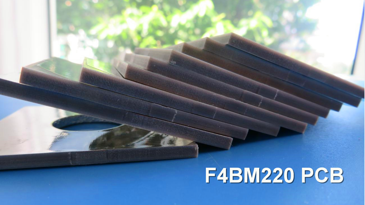
F4BM High-Frequency PCB Superior Low-Loss Substitute for Demanding RF Applications
Printed Circuit Boards are custom-made products; the images and specifications provided are for reference only.
Material Introduction
The F4BM series of high-frequency circuit board laminates are engineered by scientifically formulating and laminating a composite of fiberglass cloth, polytetrafluoroethylene (PTFE) resin, and PTFE film. This advanced manufacturing process results in superior electrical performance compared to standard F4B materials, including a broader range of dielectric constants (Dk), lower dielectric loss (Df), higher insulation resistance, and enhanced overall stability. It serves as a reliable domestic replacement for similar imported products.
A key distinction lies in the copper foil options: F4BM is clad with ED (Electrodeposited) copper foil, making it a cost-effective solution for applications with no specific Passive Intermodulation (PIM) requirements. In contrast, F4BME is paired with Reverse-Treated Foil (RTF), which provides excellent low-PIM performance, enables more precise control over fine lines, and reduces conductor loss.
By precisely adjusting the ratio of PTFE to fiberglass cloth, the F4BM and F4BME series allow for precise control over the dielectric constant while maintaining low loss and improved dimensional stability. A higher dielectric constant is achieved with a greater proportion of fiberglass, which in turn offers better dimensional stability, a lower coefficient of thermal expansion (CTE), improved temperature drift performance, and a marginally higher dielectric loss.
Features & Benefits
-DK options available: 2.17 to 3.0, customizable DK
-Low loss
-F4BME paired with RTF copper foil, excellent PIM performance
-Diverse sizes, cost-effective
-Radiation resistance, low outgassing
-Commercialized, large-scale production, high cost-effectiveness
Laminate Models and Data Sheet
| Product Technical Parameters | Product Model & Data Sheet | |||||||||||
| Product Features | Test Conditions | Unit | F4BM217 | F4BM220 | F4BM233 | F4BM245 | F4BM255 | F4BM265 | F4BM275 | F4BM294 | F4BM300 | |
| Dielectric Constant (Typical) | 10GHz | / | 2.17 | 2.2 | 2.33 | 2.45 | 2.55 | 2.65 | 2.75 | 2.94 | 3.0 | |
| Dielectric Constant Tolerance | / | / | ±0.04 | ±0.04 | ±0.04 | ±0.05 | ±0.05 | ±0.05 | ±0.05 | ±0.06 | ±0.06 | |
| Loss Tangent (Typical) | 10GHz | / | 0.001 | 0.001 | 0.0011 | 0.0012 | 0.0013 | 0.0013 | 0.0015 | 0.0016 | 0.0017 | |
| 20GHz | / | 0.0014 | 0.0014 | 0.0015 | 0.0017 | 0.0018 | 0.0019 | 0.0021 | 0.0023 | 0.0025 | ||
| Dielectric Constant Temperature Coefficient | -55ºC~150ºC | PPM/℃ | -150 | -142 | -130 | -120 | -110 | -100 | -92 | -85 | -80 | |
| Peel Strength | 1 OZ F4BM | N/mm | >1.8 | >1.8 | >1.8 | >1.8 | >1.8 | >1.8 | >1.8 | >1.8 | >1.8 | |
| 1 OZ F4BME | N/mm | >1.6 | >1.6 | >1.6 | >1.6 | >1.6 | >1.6 | >1.6 | >1.6 | >1.6 | ||
| Volume Resistivity | Standard Condition | MΩ.cm | ≥6×10^6 | ≥6×10^6 | ≥6×10^6 | ≥6×10^6 | ≥6×10^6 | ≥6×10^6 | ≥6×10^6 | ≥6×10^6 | ≥6×10^6 | |
| Surface Resistivity | Standard Condition | MΩ | ≥1×10^6 | ≥1×10^6 | ≥1×10^6 | ≥1×10^6 | ≥1×10^6 | ≥1×10^6 | ≥1×10^6 | ≥1×10^6 | ≥1×10^6 | |
| Electrical Strength (Z direction) | 5KW,500V/s | KV/mm | >23 | >23 | >23 | >25 | >25 | >25 | >28 | >30 | >30 | |
| Breakdown Voltage (XY direction) | 5KW,500V/s | KV | >30 | >30 | >32 | >32 | >34 | >34 | >35 | >36 | >36 | |
| Coefficientof Thermal Expansion | XY direction | -55 º~288ºC | ppm/ºC | 25, 34 | 25, 34 | 22, 30 | 20, 25 | 16, 21 | 14, 17 | 14, 16 | 12, 15 | 12, 15 |
| Z direction | -55 º~288ºC | ppm/ºC | 240 | 240 | 205 | 187 | 173 | 142 | 112 | 98 | 95 | |
| Thermal Stress | 260℃, 10s,3 times | No delamination | No delamination | No delamination | No delamination | No delamination | No delamination | No delamination | No delamination | No delamination | ||
| Water Absorption | 20±2℃, 24 hours | % | ≤0.08 | ≤0.08 | ≤0.08 | ≤0.08 | ≤0.08 | ≤0.08 | ≤0.08 | ≤0.08 | ≤0.08 | |
| Density | Room Temperature | g/cm3 | 2.17 | 2.18 | 2.20 | 2.22 | 2.25 | 2.25 | 2.28 | 2.29 | 2.29 | |
| Long-Term Operating Temperature | High-Low Temperature Chamber | ℃ | -55~+260 | -55~+260 | -55~+260 | -55~+260 | -55~+260 | -55~+260 | -55~+260 | -55~+260 | -55~+260 | |
| Thermal Conductivity | Z direction | W/(M.K) | 0.24 | 0.24 | 0.28 | 0.30 | 0.33 | 0.36 | 0.38 | 0.41 | 0.42 | |
| PIM | Only applicable to F4BME | dBc | ≤-159 | ≤-159 | ≤-159 | ≤-159 | ≤-159 | ≤-159 | ≤-159 | ≤-159 | ≤-159 | |
| Flammability | / | UL-94 | V-0 | V-0 | V-0 | V-0 | V-0 | V-0 | V-0 | V-0 | V-0 | |
| Material Composition | / | / | PTFE, Fiberglass Cloth F4BM paired with ED copper foil, F4BME paired with reverse-treated (RTF) copper foil. |
|||||||||
Our PCB Capability (F4BM )
| PCB Capability (F4BM) | |||
| PCB Material: | PTFE glass fiber cloth copper clad laminates | ||
| Designation (F4BM ) | F4BM | DK (10GHz) | DF (10 GHz) |
| F4BM217 | 2.17±0.04 | 0.0010 | |
| F4BM220 | 2.20±0.04 | 0.0010 | |
| F4BM233 | 2.33±0.04 | 0.0011 | |
| F4BM245 | 2.45±0.05 | 0.0012 | |
| F4BM255 | 2.55±0.05 | 0.0013 | |
| F4BM265 | 2.65±0.05 | 0.0013 | |
| F4BM275 | 2.75±0.05 | 0.0015 | |
| F4BM294 | 2.94±0.06 | 0.0016 | |
| F4BM300 | 3.00±0.06 | 0.0017 | |
| Layer count: | Single Sided, Double Sided PCB, Multilayer PCB, Hybrid PCB | ||
| Copper weight: | 0.5oz (17 µm), 1oz (35µm), 2oz (70µm) | ||
| Dielectric thickness (or overall thickness) | 0.127mm (dielectric), 0.2mm, 0.25mm, 0.5mm, 0.508mm, 0.762mm, 0.8mm, 1.0mm, 1.5mm, 1.524mm, 1.575mm, 2.0mm, 2.5mm, 3.0mm, 4.0mm, 5.0mm, 6.0mm, 8.0mm, 10.0mm, 12.0mm | ||
| PCB size: | ≤400mm X 500mm | ||
| Solder mask: | Green, Black, Blue, Yellow, Red etc. | ||
| Surface finish: | Bare copper, HASL, ENIG, Immersion silver, Immersion tin, OSP, Pure gold, ENEPIG etc.. |
A PCB and Typical Applications
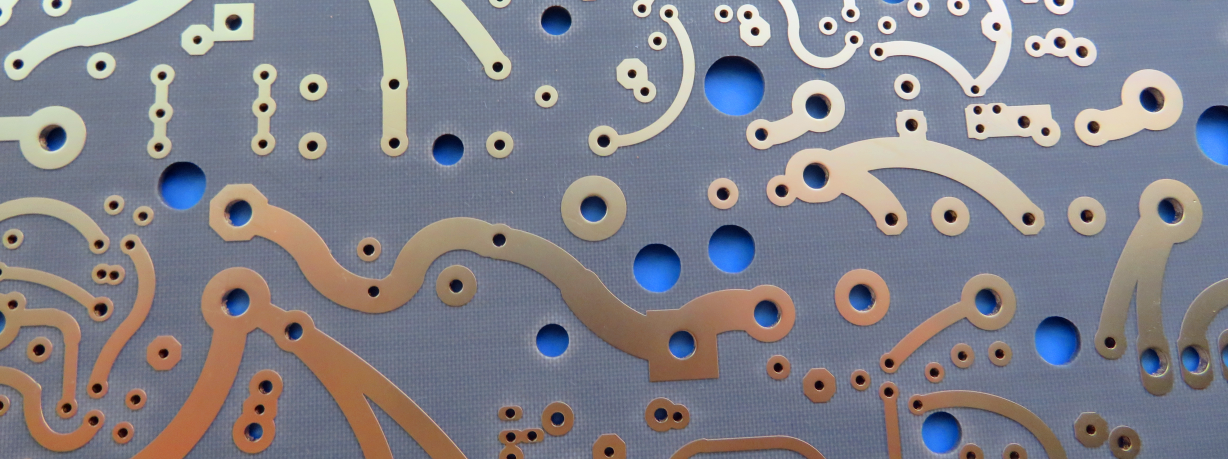
Displayed on the screen is a 2-layer copper high-frequency PCB with a low DK of 2.2, utilizing F4BM material and HASL surface finish on a 3.0mm substrate.
F4BM high-frequency PCB finds applications in microwave, RF, and radar systems, as well as in phase shifters, passive components, power dividers, couplers, combiners, feed networks, phased array antennas, satellite communications, and base station antennas.
Final - F4BM series aluminum-based/copper-based boards
These F4BM series of laminates can provide aluminum-based or copper-based materials, where one side of the dielectric layer is covered with copper foil, and the other side is covered with either aluminum-based material or copper-based , serving as shielding or heat dissipation purposes.
Model examples
F4BM220-AL represents F4BM220 with an aluminum-based substrate.