


 Home
-
Antenna PCB
-
Rogers IsoClad 917 High Frequency PCB Rogers non-woven fiberglass/PTFE PCB Materials for Antennas Application
Home
-
Antenna PCB
-
Rogers IsoClad 917 High Frequency PCB Rogers non-woven fiberglass/PTFE PCB Materials for Antennas Application
Rogers IsoClad 917 High Frequency PCB Rogers non-woven fiberglass/PTFE PCB Materials for Antennas Application
Printed Circuit Boards are custom-made products; the images and specifications provided are for reference only.
Brief Introduction
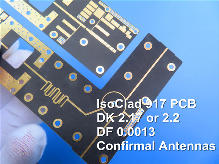
Rogers IsoClad 917 PCBs are non-woven fiberglass/polytetrafluoroethylene (PTFE) composite materials. To deliver an ultra-low dielectric constant—either 2.17 or 2.20—and a dissipation factor of 0.0013, these laminates utilize a low-proportion fiberglass-to-PTFE ratio.
A key advantage of IsoClad 917 laminate lies in its material and manufacturing design: it incorporates longer random fibers, paired with a proprietary production process. This combination enables the laminate to outperform competitors in the same product class, offering superior dimensional stability and more consistent dielectric constant across the material.
As a non-woven fiberglass-reinforced solution, IsoClad 917 PCB is less rigid compared to woven fiberglass-based laminates. This inherent flexibility makes it ideal for applications where the final printed circuit board (PCB) requires shaping or bending—such as in conformal antennas and wrap-around antennas.
.jpg)
Features
- Low dielectric constant (Dk) of 2.17 or 2.20
2. Low dissipation factor of .0013 at 10GHz
3. Extremely low loss
4. Low moisture absorption
5. Highly Isotropic in X, Y and Z Directions
Typical Applications:
- Conformal Antennas
2. Stripline and Microstrip Circuits
3. Guidance Systems
4. Radar Systems
Our PCB Capability (IsoClad 917)
| PCB Capability (IsoClad 917) | |
| PCB Material: | Non-woven Fiberglass / PTFE Composites |
| Designation: | IsoClad 917 |
| Dielectric constant: | 2.17 or 2.20 (10 GHz) |
| Dissipation factor | 0.0013 (10 GHz) |
| Layer count: | Single Sided, Double Sided, Multi-layer PCB, Hybrid PCB |
| Copper weight: | 1oz (35µm), 2oz (70µm) |
| Dielectric thickness | 20mil (0.508mm), 31mil (0.787mm), 62mil (1.575mm) |
| PCB size: | ≤400mm X 500mm |
| Solder mask: | Green, Black, Blue, Yellow, Red etc. |
| Surface finish: | ENIG(immersion gold), HASL, Immersion silver, Immersion tin, ENEPIG, OSP, Bare copper, Pure gold plated etc.. |
Appendix: Typical Values of IsoClad 917
| Typical Properties: IsoClad 917 | |||
| Property | IsoClad 917 | Condition | Test Method |
| Dielectric Constant @ 10 GHz | 2.17, 2.20 | C23/50 | IPC TM-650 2.5.5.5 |
| Dissipation Factor @ 10 GHz | 0.0013 | C23/50 | IPC TM-650 2.5.5.5 |
| Thermal Coefficient of Er (ppm/°C) | -157 | -10°C to +140°C | IPC TM-650 2.5.5.5 Adapted |
| Peel Strength (lbs.per inch) | 10 | After Thermal | IPC TM-650 2.4.8 |
| Volume Resistivity (MΩ-cm) | 1.5 x 10 10 | C96/35/90 | IPC TM-650 2.5.17.1 |
| Surface Resistivity (MΩ) | 1.0 x 10 9 | C96/35/90 | IPC TM-650 2.5.17.1 |
| Arc Resistance (seconds) | >180 | D48/50 | ASTM D-495 |
| Tensile Modulus (kpsi) | 133, 120 | A, 23°C | ASTM D-638 |
| Tensile Strength (kpsi) | 4.3, 3.8 | A, 23°C | ASTM D-882 |
| Compressive Modulus (kpsi) | 182 | A, 23°C | ASTM D-695 |
| Flexural Modulus (kpsi) | 213 | A, 23°C | ASTM D-790 |
| Dielectric Breakdown (kv) | >45 | D48/50 | ASTM D-149 |
| Density (g/cm3) | 2.23 | A, 23°C | ASTM D-792 Method A |
| Water Absorption (%) | 0.04 | E1/105 + D24/23 | MIL-S-13949H 3.7.7 IPC TM-650 2.6.2.2 |
| Coefficient of Thermal | 0°C to 100°C | IPC TM-650 2.4.24 | |
| Expansion (ppm/°C) | Mettler 3000 | ||
| X Axis | 46 | Thermomechanical | |
| Y Axis | 47 | Analyzer | |
| Z Axis | 236 | ||
| Thermal Conductivity (W/mK) | 0.263 | 100°C | ASTM E-1225 |
| Outgassing | 125°C, ≤10-6 torr | ||
| Total Mass Loss (%) | 0.02 | Maximum 1.00% | |
| Collected Volatile | 0.00 | Maximum 0.10% | |
| Condensable Material (%) | |||
| Water Vapor Regain (%) | 0.02 | ||
| Visible Condensate (±) | NO | ||
| Flammability | Meets requirements of UL94-V0 |
C48/23/50, E24/125 | UL 94 Vertical Burn IPC TM-650 2.3.10 |