| |
|
|
|
|
|
|
|
|
| |
|
| Low loss PCB |
| |
|
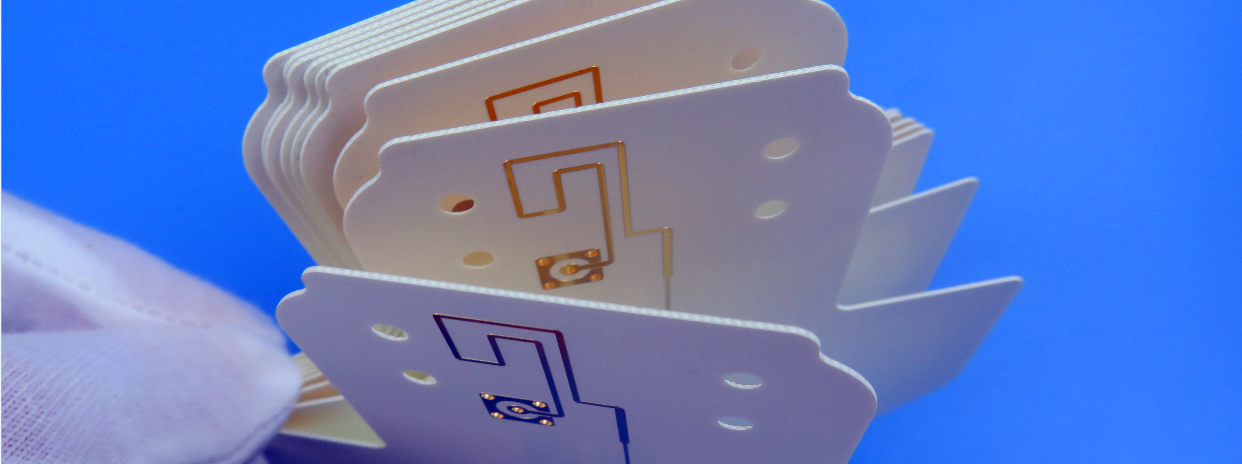
Low loss PCBs are specifically engineered to minimize signal attenuation and maintain signal integrity in high-frequency applications, making them essential in industries such as telecommunications, aerospace, and medical devices. These PCBs utilize advanced materials with low dissipation factors, typically around 0.001 to 0.002, which significantly reduce energy loss as heat during signal transmission. Additionally, they feature a stable dielectric constant that ensures consistent impedance and signal propagation, thereby minimizing distortion. High thermal conductivity is another critical characteristic, as it facilitates effective heat dissipation, enhancing the reliability and performance of the circuit board. By integrating these features, low loss PCBs provide improved signal integrity and efficiency, making them ideal for modern electronic applications where high-speed data transmission is crucial. |
|
|
.jpg) |
| Rogers TMM6 Microwave PCB 50mil 1.27mm High Frequency PCB DK 6.0 With Green Solder Mask |
Engineered for optimal RF performance, this PCB utilizes a 50-mil Rogers TMM6 substrate (DK=6.0 ± 0.05) with double-layer 1oz copper and immersion gold-plated pads for enhanced conductivity. The design incorporates 0.3mm resin-filled and copper-capped vias for improved reliability, while green solder mask protects both layers. Manufactured to IPC Class II standards, each batch of 25 boards is vacuum-sealed to ensure quality during transit, makingTMM6 PCB ideal for stable high-frequency applications. |
Tags:
Rogers TMM6 PCB |
TMM6 Printed Circuit Board |
TMM6 Microwave PCB |
TMM6 50 Mil PCB |
TMM6 High Frequency PCB |
|
|
| |
|
 |
| Kappa 438 RF PCB Rogers 60mil 1.524mm Low Loss Printed Circuit Board with Immersion Gold for Wireless Meters |
| Rogers Kappa 438 PCB bridges the gap between traditional FR-4 and premium PTFE laminates, offering controlled high-frequency performance at FR-4-compatible costs. With a dielectric constant of 4.38—closely aligned with FR-4 industry norms—Kappa 438 PCB allows seamless migration from legacy designs while cutting signal loss by over 80% at 10 GHz. Unlike expensive PTFE materials, Kappa 438 laminate requires no specialized tools: standard FR-4 processes (mechanical drilling, epoxy lamination) work seamlessly, reducing production costs by up to 90%. |
Tags:
Kappa 438 PCB Datasheet |
Kappa 438 High Frequency PCB |
Rogers Kappa 438 PCB Material |
Kappa 438 Printed Circuit Board |
Kappa 438 PCB Price |
|
|
.jpg) |
| Wangling TP1020 PCB Double Layer 5.0mm Alternative High DK RF PCB Board for GPS Antennas |
| Wangling TP1020 PCB stands out with a robust dielectric constant (DK) of 10.2, making it ideal for advanced RF and microwave applications. Wangling TP1020 PCB is constructed on 2 layers and 5.0-millimeter laminate base, featuring a hot air soldering level (HASL) surface finish and a sleek black solder mask for enhanced durability and visual clarity. Each layer incorporates 1-ounce finished copper, ensuring superior electrical conductivity and signal integrity across high-frequency circuits. |
Tags:
High DK RF PCB |
Wangling TP1020 PCB |
TP1020 DK10.2 PCB |
Alternative High DK RF PCB |
TP1020 High Frequency PCB |
|
|
| |
|
| |
|
| |
|
|
|
|