 |
Bicheng for the world! |
Business Divisions |
| |
|
| |
|
| |
|
| |
|
| |
| |
| |
Testimonials |
| |
| Kevin, Received and tested the boards - thanks very much. These are perfect, exactly what we needed. rgds Rich |
|
|
| |
| |
| |
| |
| Ruth, I got the PCB today, and they are just perfect. Please stay a little patience, my next order is coming soon. Kind regards from Hamburg Olaf |
¡ª¡ª Olaf K¨¹hnhold |
| |
| |
| |
| |
Hi Natalie. It was perfect, I attach some pictures for your reference. And I send you next 2 projects to budget. Thanks a lot again
Seba T. |
¡ª¡ª Seba T. |
| |
| |
| |
| |
|
| |
Contact us |
| |
6-11C Shidai Jingyuan, Fuyong, Baoan, Shenzhen, Guangdong, China 518103 |
| |
TEL: 86-755-27374946 |
| |
Email: sales@bicheng-enterprise.com |
| |
|
| |
 |
| |
| |
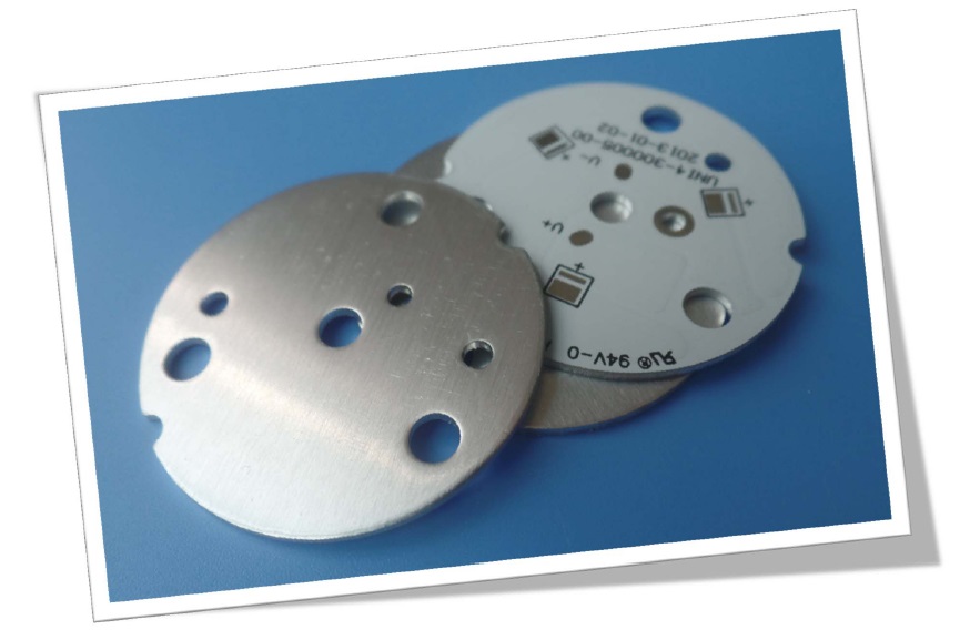
Aluminum based Sinlge Sided PCB |
|
|
|
 Business Divisions Business Divisions
To meet the demands of market, Bicheng company has set up 4 divisions, i.e. High Frequency Division, FR-4 Division, Flexible Circuit Division and MCPCB Division. |
|
|
|
|
|
General description
Metal core PCBs are thermal management circuit boards which use a base metal material as the heat dissipater part of the PCB. The metal core can be aluminum (aluminum core PCB),copper (copper core PCB) and iron (iron core PCB). They are used in high heat generating application like LED lighting in the area of high power LED lighting, automotive interior, exterior lighting, parking garage lighting, LED spot light etc. |
|
|
|
|
|
Benefit from Metal Core PCB Capabilities |
|
|
NO. |
Parameter |
Value |
1 |
Type of Metal Core |
Aluminum, Copper, Iron |
2 |
Model of Metal Core |
A1100, A5052, A6061, A6063, C1100 |
3 |
Surface Finish |
HASL, Immersion Gold, Immersion Silver, OSP |
4 |
Thickness of Surface plating |
HASL: Sn>2.54¦̀m, ENIG: Au 0.025-0.1¦̀m, Ni 2.5-5¦̀m |
5 |
Layer Count |
1-4 Layers |
6 |
Maximum of Board Size |
23" x 46" (584mm¡Á1168mm) |
7 |
Mininum of Board Size |
0.1969" x 0.1969" (5mm¡Á5mm) |
8 |
Board Thickness |
0.0157" x 0.2362" (0.4-6.0mm) |
9 |
Copper Thickness |
0.5OZ(17.5¦̀m)£¬1OZ(35¦̀m)£¬2OZ(70¦̀m)£¬3OZ(105¦̀m)£¬4OZ(140¦̀m) |
10 |
Minimum Track Width |
5mil (0.127mm) |
11 |
Minimum Space |
5mil (0.127mm) |
12 |
Minimum Hole Size |
0.012" (0.3mm) |
13 |
Maximum Hole Size |
No limit |
14 |
Minimum Holes Punched |
PCB thickness <1.0mm: 0.0394" (1.0mm) |
PCB thikness 1.2-3.0mm: 0.0591" (1.5mm) |
15 |
PTH Wall Thickness |
>20¦̀m |
16 |
Tolerance of PTH |
¡À0.00295" (0.075mm) |
17 |
Tolerance of NPTH |
¡À0.00197" (0.05mm) |
18 |
Deviation of Hole Position |
¡À0.00394" (0.10mm) |
19 |
Outline Tolerance |
Routing: ¡À0.00394" (0.1mm) |
Punching: ¡À0.00591" (0.15mm) |
20 |
Angle of V-cut |
30¡ă, 45¡ă, 60¡ă |
21 |
V-cut Size |
0.1969" x 47.24" (5mm¡Á1200mm) |
22 |
Thickness of V-cut Board |
0.0236" x 0.1181" (0.6-3mm) |
23 |
Tolerance of V-cut Angle |
¡À5o |
24 |
V-CUT Verticality |
¡Ü0.0059" (0.15mm) |
25 |
Minimum Square Slots Punched |
PCB thickness < 1.0mm: 0.0315" x 0.0315" (0.8 x 0.8mm) |
PCB thickness 1.2-3.0mm: 0.0394" x 0.0394" (1.0 x 1.0mm) |
26 |
Minimum BGA PAD |
0.01378" (0.35mm) |
27 |
Minimum Width of Solder Mask Bridge. |
8mil (0.2032mm) |
28 |
Minimum Thickness of Solder Mask |
>13¦̀m (0.013mm) |
29 |
Insulation Resistance |
1012¦¸Normal |
30 |
Peel-off Strength |
2.2N/mm |
31 |
Solder float |
260¡æ 3min |
32 |
E-test Voltage |
50-250V |
33 |
Thermal Conductivity |
0.8-8W/M.K |
34 |
Warp or Twist |
¡Ü0.5% |
35 |
Flammability |
FV-0 |
36 |
Minimum Height of Component indicator |
0.0059"(0.15mm) |
37 |
Minimum Open Solder Mask on Pad |
0.000394" (0.01mm) |
|
|
|
|
|
|
|
|
|
|
|
|
|
|
|