|
|
|
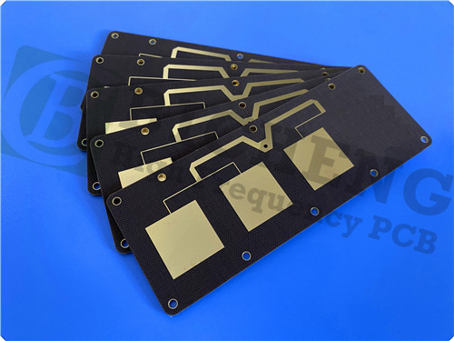
TLX Serie 2-layer Low DK2.55 Taconic TLX-8 High Frequency PCB 30mil Immersion Gold |
|
|
|
|
|
|
|
1. Introduction of TLX-8
TLX-8 is a type of PTFE fiberglass laminate, recognized for its reliability across various RF applications. This versatile material is available in a range of thicknesses and copper cladding options, making it ideal for low layer count microwave designs. It provides mechanical reinforcement in substrates that must withstand harsh environments, such as:
- Resistance to creep in printed wiring boards (PWBs) that are bolted to housings subject to high vibration during space launches
- Endurance against high temperatures in engine modules
- Radiation resistance for use in space (refer to NASA’s guidelines on low outgassing materials)
- Durability in extreme marine conditions for warship antennas
- Resilience across a wide temperature range for altimeter substrates during flight.
|
|
|
|
2. Benefits
- Outstanding PIM values in PCBs, measured at less than -160 dBc
- Exceptional mechanical and thermal properties
- Low and stable dielectric constant (Dk)
- Dimensionally stable
- Minimal moisture absorption
- Tightly controlled dielectric constant
- Low dielectric loss (DF)
- UL 94 V0 rated
- Ideal for low layer count microwave designs
|
|
|
|
3. Main Properties
- Electrical Properties
Dielectric Constant @ 10 GHz - 2.55 ± 0.04 - IPC-650 2.5.5.3
Dissipation Factor @ 10 GHz - 0.0018 - IPC-650 2.5.5.5.1
|
|
|
|
Surface Resistivity Elevated Temp. 6.605 x 10^8 Mohm IPC-650 2.5.17.1 Sec. 5.2.1
Surface Resistivity Humidity Cond. 3.550 x 10^6 Mohm IPC-650 2.5.17.1 Sec. 5.2.1
Volume Resistivity Elevated Temp. 1.110 x 10^10 Mohm/cm IPC-650 2.5.17.1 Sec. 5.2.1
Volume Resistivity Humidity Cond. 1.046 x 10^10 Mohm/cm IPC-650 2.5.17.1 Sec. 5.2.1 |
|
|
|
- Dimensional Stability
MD After Bake 0.06 mm/M (mils/in) IPC-650 2.4.39 Sec. 5.4
CD After Bake 0.08 mm/M (mils/in) IPC-650 2.4.39 Sec. 5.4
MD Thermal Stress 0.09 mm/M (mils/in) IPC-650 2.4.39 Sec. 5.5
CD Thermal Stress 0.10 mm/M (mils/in) IPC-650 2.4.39 Sec. 5.5 |
|
|
|
- CTE (25-260 °C)
X - 21 ppm/°C - IPC-650 2.4.41/ASTM D 3386
Y - 23 ppm/°C - IPC-650 2.4.41/ASTM D 3386
Z - 215 ppm/°C - IPC-650 2.4.41/ASTM D 3386 |
|
|
|
- Td
2% Weight Loss - 535 °C - IPC-650 2.4.24.6 (TGA)
5% Weight Loss - 553 °C - IPC-650 2.4.24.6 (TGA) |
|
|
|
-Chemical / Physical Properties
Moisture Absorption - 0.02 % IPC-650 2.6.2.1
Dielectric Breakdown - > 45 Kv - IPC-650 2.5.6
Flammability Rating - V-0 - UL-94 |
|
|
|
4. PCB Stackup: 2-layer rigid PCB
Copper_layer_1 - 35 μm
Taconic TLX-8 Core - 0.762 mm (30mil)
Copper_layer_2 - 35 μm |
|
|
|
| 5. PCB Construction Details: |
| |
| - Board dimensions: 85mm x 77 mm=1PCS, +/- 0.15mm
- Minimum Trace/Space: 5/5 mils
- Minimum Hole Size: 0.3mm
- No Blind vias.
- Finished board thickness: 0.8mm
- Finished Cu weight: 1oz (1.4 mils) outer layers
- Via plating thickness: 20 μm
- Surface finish: Immersion Gold
- Top Silkscreen: White
- Bottom Silkscreen: No
- Top Solder Mask: No
- Bottom Solder Mask: No
- 100% Electrical test used prior to shipment |
| |
| |
|
 |
|
|
|
|
6. PCB Statistics:
Components: 26
Total Pads: 48
Thru Hole Pads: 25
Top SMT Pads: 23
Bottom SMT Pads: 0
Vias: 32
Nets: 2 |
|
|
|
7. Type of artwork supplied: Gerber RS-274-X |
|
|
|
8. Accepted standard: IPC-Class-2 |
|
|
|
9. Availability: worldwide |
|
|
|
10. Some Typical Applications:
- radar systems
- mobile communications
- microwave test equipment
- microwave transmission devices
- couplers, splitters, combiners, amplifiers, antennas |
|
|
|
|
|
|
|
|
|
|
|
|
|
NEXT:TU-768 High Tg180 High Frequency 60mil Double Sided PCB with HASL and Green Solder Mask |
|
|
|
|
|
|