| |
|
|
|
|
|
|
|
|
White-Flexible-Printed-Circuit-on-PET-with-White-Solder-Mask-and-Immersion-Gold-for-Capacitive-Touch-Screen-and-Panel |
|
|
(Flexible printed circuits are custom-made products. The picture and parameters shown are for reference only.) |
|
|
|
|
|
General description |
|
|
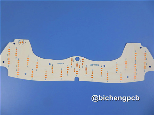
This dual-layer flexible printed circuit utilizes PET substrate with 1oz copper thickness per conductive layer. The construction features white solder mask coating and immersion gold (ENIG) surface finish on all contact pads. Specifically designed for printer applications, the FPC incorporates strategically bulged pads to ensure reliable interconnection stability during dynamic operation. |
|
|
|
|
|
FPC Specifications |
|
|
PCB SIZE |
172 x 145mm=1PCS |
Base Material: |
PET |
Number of Layers |
Double sided PCB |
SMT |
n/a |
Through Hole Components |
no |
LAYER STACKUP |
Copper ------- 35um(1oz) |
|
Adhesive |
|
PET |
|
Adhesive |
|
Copper ------- 35um(1oz) |
Minimum Trace and Space: |
4mil/8mil |
Minimum / Maximum Holes: |
1.2mm/ 3.5mm |
Final foil external: |
1oz |
Final foil internal: |
0oz |
Final height of PCB: |
0.25mm ±0.05 |
Surface Finish |
Immersion gold |
Solder Mask Apply To: |
TOP, Bottom |
Solder Mask Color: |
White Coverlay |
CONTOUR/CUTTING |
Punching |
Stiffener: |
PET on back of gold finger area |
Side of Component Legend |
NO |
Colour of Component Legend |
NO |
VIA |
Plated Through Hole(PTH) |
FLAMIBILITY RATING |
UL 94-V0 Approval MIN. |
TEST |
100% Electrical Test prior shipment |
TYPE OF ARTWORK TO BE SUPPLIED |
email file, Gerber RS-274-X, PCBDOC etc |
SERVICE AREA |
Worldwide, Globally. |
|
|
|
|
|
|
.jpg) |
|
|
|
|
|
Features and Benefits
1. Excellent flexibility
2. Reducing the volume
3. Weight reduction
4. Consistency of assembly
5. More than 18+ years of PCB experience
6. Customer complaint rate: <1%
7. Prototype capability
8. Volume Production capability |
|
|
|
|
|
Applications |
|
|
Capacitive touch screen / panel, Industrial control temperature controller soft board, consumer card reader soft board |
|
|
|
|
|
Covercoat / Solder Mask |
|
|
In flexible circuit manufacturing, the covercoat serves a critical protective function distinct from rigid PCB solder masks. This polyimide-based film, coated with specialized semi-cured adhesive, undergoes thermal lamination to create a durable encapsulation around copper traces while maintaining clean pad exposures through engineered access points.
Production protocols dictate the covercoat panel dimensions to be slightly reduced compared to the base FPC panel. This intentional undersizing prevents edge sealant issues that might otherwise lead to air entrapment and potential delamination in the final product.
Tooling hole alignment forms the foundation for precise layer registration between covercoat and circuit panels. Access hole creation methods vary by production scale - drilling remains standard for prototype and low-volume work (typically in 5-10 panel stacks), while punching becomes the preferred method for cost-effective mass production.
Drilling parameter optimization presents unique challenges with covercoat materials. The polyimide substrate's thermal characteristics, combined with the lack of conductive copper layers, require specific adjustments to achieve clean hole quality without material damage.
Large panel processing introduces additional complexity, necessitating up to 0.2% dimensional compensation to account for flexible substrate variations. This correction ensures consistent quality across full production panels despite material movement during fabrication. |
|
|
|
|
|
FPC Capabilities 2025 |
|
|
No. |
Specifications |
Capabilities |
1 |
Board Type |
Single layer, Doulbe layer, Multilayer, Rigid-Flex |
2 |
Base Material |
PI, PET |
3 |
Copper Weight |
0.5oz, 1oz, 2oz |
4 |
LED Maximum Size |
250 x 5000mm |
5 |
General Maximum Size |
250 x 2000mm |
6 |
Board Thickness |
0.03mm-3.0mm |
7 |
Thickness Tolerance |
±0.03mm |
8 |
Mininum Drill Hole |
0.05mm |
9 |
Maximum Drill Hole |
6.5mm |
10 |
Tolerance of Drill Hole |
±0.025mm |
11 |
Thickness of Hole Wall |
≧ 8 um |
12 |
Minimum Track/Gap of Single Layer Board |
0.025/0.03mm |
13 |
Minimum Track/Gap of Double Layer and Multilayer Board |
0.03/0.040mm |
14 |
Etching Tolerance |
±0.02mm |
15 |
Minimum Width of Silk Legend |
≧ 0.125mm |
16 |
Minimum Heigh of Silk Legend |
≧0.75mm |
17 |
Distance from Legend to Pad |
≧0.15mm |
18 |
Distance from Opening Solder Mask of Drill Coverlay to Track |
≧0.03mm |
19 |
Distance from Opening Solder Mask of Punching Coverlay to Track |
≧0.03mm |
20 |
Thickness of Immersion Nickel |
100-300u" |
21 |
Thickness of Immersion Gold |
1-3u" |
22 |
Thicnkess of Immersion Tin |
150-400u" |
23 |
Minimum Electrical Testing Pad |
0.2mm |
24 |
Minimum Tolerance of Outline(Normal Steel Mould Punch) |
±0.1mm |
25 |
Minimum Tolerance of Outline (Precision Steel Mould Punch) |
±0.05mm |
26 |
Mininum Radius of Bevel Angle (Outline) |
0.2mm |
27 |
Stiffner Material |
PI, FR-4, 3M Adhesive, PET, Steel Sheet |
28 |
RoHs |
Yes |
29 |
Solder Mask Colour |
Yellow, White, Black, Green |
|
|
|
|
|
|
More Displays of White Flex |
|
|
.jpg) |
|
|
|
|
|
 |
|
|
|
|
|
|
|
|
|
|
|
Hot Tags:
Dual Layer Flexible Circuit |
Flexible PET Substrate |
Immersion Gold PET PCB |
PTH Flexible PCB |
White Solder Mask Laminate |
|
|
|
