|

|
|
|
|
|
What Circuit Boards Do We Do? (59)
|
|
|
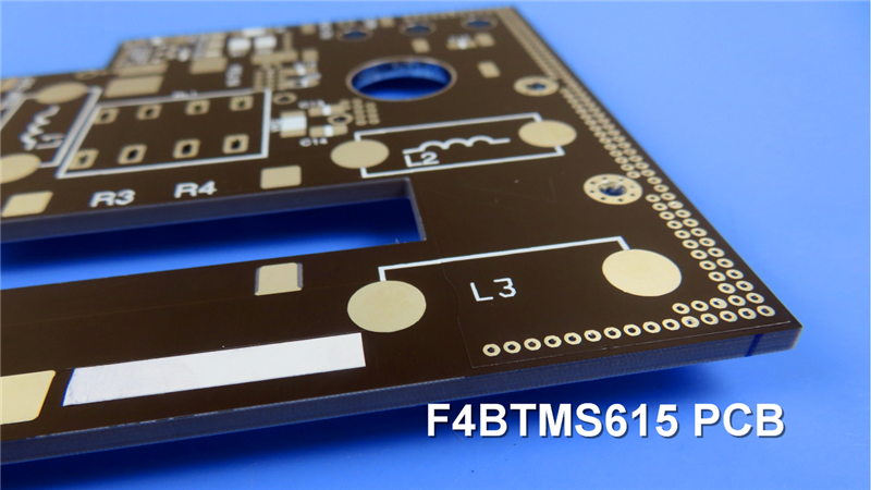
F4BTMS High Frequency PCB
|
|
|
|
|
|
Introduction |
|
|
The F4BTMS series is an upgraded version of the F4BTM series. The material now incorporates a large amount of ceramics and utilizes ultra-thin and ultra-fine fiberglass cloth reinforcement. These enhancements have greatly improved the material's performance, resulting in a wider range of dielectric constants. |
|
|
|
|
|
The incorporation of ultra-thin, ultra-fine fiberglass cloth reinforcement, along with a precise blend of special nanoceramics and polytetrafluoroethylene resin, minimizes electromagnetic wave interference, reducing dielectric loss and enhancing dimensional stability. |
|
|
|
|
|
F4BTMS exhibits reduced anisotropy in the X/Y/Z directions, enabling higher frequency usage, increased electrical strength, and improved thermal conductivity. |
|
|
|
|
|
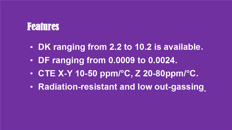
Features |
|
|
F4BTMS material offers a wide range of dielectric constants, providing flexible options from 2.2 to 10.2, while maintaining a stable value throughout. |
|
|
|
|
|
Its dielectric loss is extremely low, ranging from 0.0009 to 0.0024, minimizing energy dissipation and improving overall system efficiency. |
|
|
|
|
|
F4BTMS exhibits excellent temperature coefficient of dielectric constant. The TCDK with a DK value ranging from 2.55 to 10.2, remains within 100 ppm/⊥. |
|
|
|
|
|
The CTE values in the X and Y directions are between 10-50 ppm/°C , while in the Z direction, it is as low as 20-80 ppm/°C. This low thermal expansion ensures exceptional dimensional stability, enabling reliable hole copper connections. |
|
|
|
|
|
F4BTMS demonstrates remarkable resistance to radiation, retaining stable dielectric and physical properties even after exposure to irradiation; and low outgassing performance, meeting the vacuum outgassing requirements for aerospace applications. |
|
|
|
|
|
|
|
|
|
|
|
PCB capability |
|
|
We offer a wide range of PCB manufacturing capabilities, allowing you to choose the best options for your needs. |
|
|
|
|
|
We can accommodate various layer counts, including Single Sided, Double Sided, Multilayer, and Hybrid PCBs. |
|
|
|
|
|
You can select from different copper weights, such as 1oz (35µm) and 2oz (70µm). |
|
|
|
|
|
We offer a diverse selection of dielectric thicknesses, ranging from 0.09mm (3.5mil) to 6.35mm (250mil). |
|
|
|
|
|
Our manufacturing capabilities support PCB sizes up to 400mm X 500mm, catering to designs of different scales. |
|
|
|
|
|
Various solder mask colors are available, such as Green, Black, Blue, Yellow, Red, and more. |
|
|
|
|
|
Moreover, we provide diverse surface finish options, including Bare copper, HASL, ENIG, Immersion silver, Immersion tin, OSP, Pure gold and ENEPIG etc. |
|
|
|
|
|
| |
PCB Capability (F4BTMS) |
PCB Material: |
PTFEㄛUltra-thin and ultra-fine fiberglass, ceramics. |
Designation (F4BTMS ) |
F4BTMS |
DK (10GHz) |
DF (10 GHz) |
F4BTMS220 |
2.2±0.02 |
0.0009 |
F4BTMS233 |
2.33±0.03 |
0.0010 |
F4BTMS255 |
2.55±0.04 |
0.0012 |
F4BTMS265 |
2.65±0.04 |
0.0012 |
F4BTMS294 |
2.94±0.04 |
0.0012 |
F4BTMS300 |
3.0±0.04 |
0.0013 |
F4BTMS350 |
3.5±0.05 |
0.0016 |
F4BTMS430 |
4.3±0.09 |
0.0015 |
F4BTMS450 |
4.5±0.09 |
0.0015 |
F4BTMS615 |
6.15±0.12 |
0.0020 |
F4BTMS1000 |
10.2±0.2 |
0.0020 |
Layer count: |
Single Sided, Double Sided PCB, Multilayer PCB, Hybrid PCB |
Copper weight: |
0.5oz (17 µm), 1oz (35µm), 2oz (70µm) |
Dielectric thickness |
0.09mm (3.5mil), 0.127mm (5mil), 0.254mm(10mil),0.508mm(20mil), 0.635mm(25mil), 0.762mm(30mil), 0.787mm(31mil), 1.016mm(40mil), 1.27mm(50mil), 1.5mm(59mil), 1.524mm(60mil), 1.575mm(62mil), 2.03mm(80mil), 2.54mm(100mil), 3.175mm(125mil), 4.6mm(160mil), 5.08mm(200mil), 6.35mm(250mil) |
PCB size: |
≒400mm X 500mm |
Solder mask: |
Green, Black, Blue, Yellow, Red etc. |
Surface finish: |
Bare copper, HASL, ENIG, Immersion silver, Immersion tin, OSP, Pure gold, ENEPIG etc.. |
|
|
|
|
|
|
|
Applications |
|
|
F4BTMS PCBs have extensive applications across various domains, including Aerospace and aviation equipment, Microwave and RF applications, Radar systems, Signal distribution feed networks, Phase-sensitive antennas and phased array antennas etc. |
|
|
|
|
|
Thank you. I*ll see you next time. |
|
|
|
|
|
|
|
|
|
|
|
|
|
|
|
|
|
|