| |
 |
| |
|
|
|
|
|
| |
|
What is Test Coupon in High Frequency PCB ? |
|
|
|
| |
|
1. Definition of Test Coupon |
|
|
|
| |
|
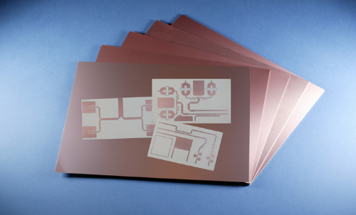
In high-frequence PCBs, test coupon is small, dedicated area on board panel for testing and evaluation, representing board's material and manufacturing characteristics related to high-frequency performance. |
|
|
| |
|
|
|
|
| |
|
2.Purposes of Test Coupon |
|
|
| |
|
2.1 Material Property Verification
Test coupon verifies dielectric properties of PCB materials like dielectric constant and loss tangent, which are crucial for high - frequency applications. It ensures that the actual properties meet the specifications. Lower dielectric constant reduces signal delay and crosstalk. Loss tangent affects signal attenuation.
2.2 Process Monitoring
Monitors manufacturing process. High-freq PCBs need precise techniques. Test coupon checks process quality, e.g., copper trace thickness and uniformity important for signal integrity. Deviations indicate manufacturing problems.
2.3 Signal Integrity Testing
Crucial for evaluating signal integrity. In high-frequence circuits, signals affected by various factors. Test coupon provides platform to test transmission line impedance. Strict control of impedance ensures correct signal transmission. Technologies measure impedance profile. Adjust design or process if necessary. |
|
|
| |
|
|
|
|
| |
|
3. Design Considerations |
|
|
| |
|
3.1 Location
Place in area representing actual circuit environment, usually at panel edge or similar manufacturing condition area to active circuit. Different temperature gradient between center and edge may lead to inaccurate test results.
3.2 Size and Shape
Designed for accurate testing with sufficient material and trace lengths. Needs enough area for multiple test points and different test structures. For impedance testing, may have different length and width transmission line segments.
3.3 Connectivity
Connect to board for testing. Access points or pads connect test equipment. Design should reduce parasitic effects. Low inductance connection between pads and traces avoids noise.
|
|
|
| |
|
|
|
|
| |
|
4. Advantages of Rogers RT/duroid 6202 PCB in Test Coupon Testing |
|
|
| |
|
When discussing the tensile modulus in high-frequency PCBs, Rogers RT/duroid 6202 PCB immediately comes to my mind. Rogers RT/duroid 6202 is a glass - fiber - reinforced laminate with low loss and a low dielectric constant. It can provide excellent electrical and mechanical properties, meeting the design requirements of complex microwave structures that demand mechanical reliability and electrical stability. |
|
|
| |
|
|
|
|
| |
|
 |
|
|
| |
|
|
|
|
| |
|
4.1 Electrical Performance Advantages |
|
|
| |
|
Low Dielectric Constant and Stable Loss:The dielectric constant is 2.94 ± 0.04 at 10GHz and the dissipation factor is as low as 0.0015@10GHz. This ensures low signal transmission loss and delay in high - frequency signal transmission testing of the Test Coupon, safeguarding signal integrity.
Precise Impedance Control:With its stable low - dielectric and low - loss characteristics, it helps obtain accurate data in impedance testing, facilitating the optimization of circuit design.
Excellent Insulation Performance:The surface resistance is 10 to the ninth power Mohm, and the volume resistivity is about 10 to the sixth power Mohm ·cm. This effectively prevents signal leakage and coupling between adjacent circuit components on the Test Coupon, ensuring the accuracy of test results. |
|
|
| |
|
|
|
|
| |
|
4.2 Thermal Stability Advantages |
|
|
| |
|
Small Variation of Dielectric Constant with Temperature:The temperature coefficient of the dielectric constant (TCDk) is 13ppm/°C. The dielectric constant fluctuates slightly at different temperatures, reducing the interference of temperature on test results.
Fast Heat Dissipation:The thermal conductivity is 0.69W/m·K. It can dissipate heat rapidly, preventing performance degradation and inaccurate test results caused by overheating during high - power testing. |
|
|
| |
|
|
|
|
| |
|
4.3 Mechanical Performance Advantages |
|
|
| |
|
Good Dimensional Stability:Reinforced with glass fiber cloth, the elongation rate is 0.05 - 0.07mil/inch. It resists deformation during manufacturing and testing, ensuring accuracy.
High Strength:The tensile modulus is 2070MPa, the tensile strength is 48MPa, and the flexural strength is 62MPa. It can withstand external forces and stresses, ensuring smooth testing.
Good Compatibility:The glass transition temperature (Tg) is 280°C, and it can endure multiple reflows at a peak temperature of 288°C. It is compatible with lead - free assembly processes, without affecting material properties and test results. |
|
|
| |
|
|
|
|
| |
|
4.4 Environmental Adaptability Advantages |
|
|
| |
|
Low Moisture Absorption Rate:The water absorption rate is less than 0.04%. Its performance remains stable in a humid environment, reducing the interference of humidity on test results.
Good Chemical Resistance:Composed of PTFE fluoropolymer resin, etc., it is resistant to solutions and reagents used in etching and electroplating processes, maintaining material stability during manufacturing. |
|
|
| |
|
|
|
|
| |
|
5.Specification Parameter Table of Rogers RT/duroid 6202 |
|
|
| |
|
Items |
Details |
Standard Thicknesses |
0.005" (0.127mm) +/- 0.0005"
0.020" (0.508mm) +/- 0.0010"
0.030" (0.762mm) +/- 0.0010"
(Additional non-standard thicknesses available from 0.005" - 0.060" in varying increments) |
Standard Panel Sizes |
12" X 18" (305mm X 457mm)
24" X 18" (610mm X 457mm)
(Additional panel sizes available) |
Standard Claddings |
Electrodeposited Copper Foil:
½ oz. (18μm) HH/HH
1 oz. (35μm) H1/H1
Rolled Copper Foil:
½ oz. (18μm) SR/SR
1 oz. (35μm) 1R/1R
(Additional claddings and cladding weights, such as resistive foil and reverse treated ED are available) |
|
|
|
| |
|
|
|
|
| |
|
6. Conclusion |
|
|
| |
|
Test Coupon, the linchpin of high-frequency PCB validation, holds the key to unlocking the full potential of intricate circuit designs. |
|
|
| |
|
|
|
|
| |
|
Founded in 2003, Shenzhen Bicheng Electronics Technology Co., Ltd is an established high frequency PCB supplier and exporter in Shenzhen, China, serving customers worldwide.
We are devoted to delivering high-frequency PCB products and solutions of the highest quality, along with customized service. Feel free to consult and contant at any time !
Visit https://www.bicheng-enterprise.com to learn more.
Unlock its full potential by contacting Vicky at v.xie@bichengpcb.com. |
|
|
| |
|
|
|
|
| |
|
|
|
|
| |
|
|
|
|
| |
|
|
|
| |
|
|
|
| |
|
|
|
|
|