| |
 |
| |
|
|
|
|
|
| |
|
What is PIM in High Frequency PCB? |
|
|
|
| |
|
1. The Introduction of PIM |
|
|
|
| |
|
Passive Intermodulation (PIM) has been an issue in wireless transmission systems since the 1970s. In high - frequency PCB, PIM refers to the generation of unwanted signals when two or more signals interact in passive components like connectors, cables, and PCBs. These spurious signals can interfere with the original signals and degrade the performance of high - frequency communication systems. Minimizing PIM requires evaluating antennas in cell sites or wireless base stations.And Low-PIM antennas begin with excellent PCB laminates that can hold their own against PIM. |
|
|
| |
|
|
|
|
| |
|
2. Industry Standards of PIM |
|
|
| |
|
In the communications industry, there are strict requirements for Passive Intermodulation (PIM). Generally speaking, when the power of two carrier signals is +43 dBm, the acceptable PIM indicators for passive components within the industry usually range from -100 dBm to -120 dBm. For example, in the construction of base stations, passive components such as antennas, cables, and connectors used must meet the corresponding PIM standards to ensure the normal operation of the base stations and the quality of signal transmission. Otherwise, it may lead to an increase in the noise floor of the base station receivers, affect the performance of the base stations, reduce the capacity of the communication network, and lower the user experience. |
|
|
| |
|
|
|
|
| |
|
3. Exploring the Impact of PIM |
|
|
| |
|
With each new generation of wireless communication technologies, the effects of PIM are more apparent. For instance, in a 5G base station deployment, even a small amount of PIM can cause significant signal interference. This leads to degraded data transmission speeds and unreliable connections. Another case could be in satellite communication systems where PIM can disrupt the signal between the satellite and the ground station. |
|
|
| |
|
|
|
|
| |
|
4. Rogers AD Series - Superior PIM & Circuit Loss Features |
|
|
| |
|
Rogers AD Series antenna products are made from glass-reinforced, PTFE-based materials, offering controlled dielectric constant, low loss performance, and excellent PIM performance. Additionally, these products come with standard electrodeposited (ED) or reverse treated ED copper foil options, providing sufficient choices that help minimize circuit losses and antenna PIM. In this context, we will take the Rogers AD350A laminate from the AD Series antenna products as an example for further explanation. |
|
|
| |
|
|
|
|
| |
|
5. Insight into Rogers AD350A PCB |
|
|
| |
|
Rogers AD350A PCB demonstrates outstanding PIM performance, achieving -159 dBC at 30 mil and -163 dBC at 60 mil. AD350A Substrate also has very low moisture absorption (less than 0.1%), very high copper peel strength (14.7 pli) and very high decomposition temperature exceeding 500°C. Now,let's take a closer look at Rogers AD350A. |
|
|
| |
|
|
|
|
| |
|
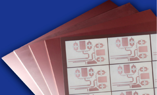
5-1. Rogers AD350A PCBs |
|
|
| |
|
 |
|
|
| |
|
|
|
|
| |
|
5.1 Features and Benefits |
|
|
| |
|
Low loss tangent (loss tangent of 0.003 at 10 GHz and 23°C at 50% relative humidity)
• Excellent circuit performance in all typical wireless frequency bands
Controlled dielectric constant ( 3.5 -/- 0.05 at 10 GHz/23°C. ±0.05)
• Repeatable circuit performance
Very low PIM (-159 dBc at 30 mil, and -163 dBC at 60 mil )
• Excellent antenna performance and reduced yield loss
Excellent dimensional stability
• Repeatable circuit performance and improved manufacturing yields
Outstanding thermal conductivity(0.44 W/m-K)
• Ensures effective heat dissipation and optimal performance
Low Z-axis thermal expansion(35 ppm/°C)
• Maintains board structural integrity and reduces risk of mechanical stress or failure |
|
|
| |
|
|
|
|
| |
|
5.2 Typical Applications |
|
|
| |
|
• Cellular infrastructure base station antenna
• Automotive telematics antenna systems
• Commercial satellite radio antenna |
|
|
| |
|
|
|
|
| |
|
5-2. Typical Standard Offerings
Product |
Standard Thickness |
Standard Panel Sizes |
Standard Claddings |
AD350A |
0.030" (0.762mm) +/- 0.002"
0.060" (1.524mm) +/- 0.003"
0.120" (3.048mm) +/- 0.006"
|
12" X 18"
(305 X 457mm)
24" X 18"
(610 X 457mm) |
Electrodeposited Copper Foil
½ oz. (18μm) HH/HH
1 oz. (35μm) H1/H1
Reverse Treated Electrodeposited Copper Foil
½ oz. (18μm) RH/RH
1 oz. (35μm) R1/R1
|
|
|
|
| |
|
|
|
|
| |
|
6.Final Thoughts |
|
|
| |
|
As we strive for optimal functioning in wireless communication, PIM in high frequency PCB can't be ignored. PIM in high frequency PCB may seem like a mystery, but unlocking its secrets is the key to unlocking superior wireless communication performance. The Rogers AD Series laminates feature low loss, low thermal expansion, excellent thermal performance, and outstanding PIM performance, making them an ideal choice for antenna applications. |
|
|
| |
|
|
|
|
| |
|
Founded in 2003, Shenzhen Bicheng Electronics Technology Co., Ltd is an established high frequency PCB supplier and exporter in Shenzhen, China, serving customers worldwide.
We are devoted to delivering high-frequency PCB products and solutions of the highest quality, along with exceptional service ! |
|
|
| |
|
|
|
|
| |
|
|
|
|
| |
|
|
|
|
| |
|
|
|
| |
|
|
|
| |
|
|
|
|
|