| |
 |
| |
|
|
|
|
|
| |
|
What is IPC-Class-2 in High Frequency PCB ? |
|
|
|
| |
|
1. IPC Standards Overview |
|
|
|
| |
|
The IPC is a global trade association that develops and maintains electronics industry standards, covering design, manufacturing, and assembly of PCBs. IPC-Class-2 is an intermediate standard between Class-1 (general-purpose) and Class-3 (high-reliability). |
|
|
| |
|
|
|
|
| |
|
2. Requirements for High-Frequency PCB in IPC-Class-2 |
|
|
| |
|
2.1 Design Requirements
Trace Spacing/Width: Precise control needed. Tolerances more stringent than Class-1 for consistent electrical performance. E.g., ±0.1mm trace width tolerance.
Layer Stack-up: Consider dielectric constant and loss tangent. Optimize to minimize signal loss and impedance discontinuities. Use materials with stable dielectric constant.
2.2 Manufacturing Requirements
Drilling/Hole Quality: Must meet quality standards. Hole diameter tolerance within specific range (e.g., ±0.075mm). Smooth hole wall for impedance stability.
Surface Finish: ENIG often used. Gold layer thickness controlled (0.05 - 0.15μm) for good contact resistance and corrosion resistance.
2.3 Testing/Inspection Requirements
Electrical Testing: Impedance testing important. Tolerance ±10% of designed value. Measured with VNA for minimal loss/distortion.
Visual Inspection: More detailed than Class-1. Check for defects. Max scratch length on critical area might be 0.5mm. |
|
|
| |
|
|
|
|
| |
|
3. Key Technical Indicators of IPC - Class - 2 High - frequency PCBs |
|
|
| |
|
Electrical Performance
Dielectric Constant (Dk) range
Low Dissipation Factor (Df)
Characteristic Impedance (Z0) tolerance
Physical Properties
Copper foil thickness & roughness
Board thickness & dimensional accuracy
Dielectric layer thickness & uniformity
Environmental Adaptability
Temperature resistance range
Low moisture absorption rate
Chemical resistance |
|
|
| |
|
|
|
|
| |
|
4. Merits of RT/duroid 5870 PCB |
|
|
| |
|
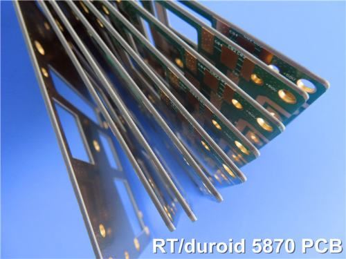
When it comes to PCBs that comply with IPC Class 2, the one that impresses me the most is Rogers RT/duroid 5870 high frequency PCB.
Rogers RT/duroid 5870 PCB represents a leading choice in high-frequency laminates within PCB technology. Made from PTFE composites reinforced with glass microfibers, these laminates offer outstanding dielectric properties, making them perfect for applications that require high frequency, minimal dispersion, and low losses. It is worth mentioning that the exceptional uniformity of the dielectric constant stems from the random orientation of its microfibers.Let's delve into the key details and benefits of this remarkable product. |
|
|
| |
|
|
|
|
| |
|
4-1. Rogers RT/duroid 5870 PCB |
|
|
| |
|
 |
|
|
| |
|
|
|
|
| |
|
4-2. Characteristics and Advantages of RT/duroid 5870 Laminate |
|
|
| |
|
Feature |
Description |
Advantage |
Dielectric Constant (Dk) |
2.33 ± 0.02 at 10 GHz and 23°C. |
Offers stable electrical properties for accurate signal transmission at high frequencies. |
Dissipation Factor |
0.0012 at 10 GHz; 0.0005 at 1MHz. |
Ensures low signal loss and high signal integrity. |
Copper Peel Strength |
27.2 pli. |
Provides strong adhesion between copper and the substrate, enhancing the mechanical stability of the PCB. |
Low Moisture Absorption |
0.02%. |
Reduces the risk of degradation due to moisture, ensuring reliable performance in humid environments. |
Thermal Performance |
Td > 500 °C TGA. |
Allows the PCB to withstand high temperatures without degradation. |
Coefficient of Thermal Expansion (CTE) |
X-axis: 22 ppm/°C; Y-axis: 28 ppm/°C; Z-axis: 173 ppm/°C. |
Helps to minimize thermal stress and prevent delamination or warping during temperature changes. |
Flammability |
Meets UL 94-V0. |
Provides a high level of fire safety, reducing the risk of fire hazards in electronic devices. |
Isotropic Nature |
Ensures consistent performance across all axes. |
Guarantees uniform electrical and mechanical properties in all directions, enhancing the reliability and performance of the PCB. |
Chemical Resistance |
Resists etching, electroplating chemicals. Endures processes well. |
Ensures quality, meets IPC-Class-2 process needs. |
Environmental Friendliness |
Halogen-free, RoHS compliant. Low environmental impact. |
Meets IPC-Class-2 environmental standards. |
High Strength |
Micro-glass fiber reinforced, resists stress. |
Secures structural integrity, meets strength reqs. |
Good Machinability |
Easy to cut, shape. Helps production, cuts cost. |
Fits IPC-Class-2 manufacturability. |
|
|
|
| |
|
|
|
|
| |
|
5. Applications |
|
|
| |
|
Commercial Airline Broadband Antennas
Microstrip and Stripline Circuits
Millimeter Wave Applications
Radar Systems
Guidance Systems
Point-to-Point Digital Radio Antennas |
|
|
| |
|
|
|
|
| |
|
6. End Note |
|
|
| |
|
In the high-frequency PCB realm, IPC-Class-2 is crucial. It's a linchpin ensuring precision and reliability, the bedrock for seamless signal transmission and optimal performance. Also a game-changer setting quality and performance standards, and the driving force behind efficient signal transfer and dependable operation. |
|
|
| |
|
|
|
|
| |
|
Founded in 2003, Shenzhen Bicheng Electronics Technology Co., Ltd is an established high frequency PCB supplier and exporter in Shenzhen, China, serving customers worldwide.
We are devoted to delivering high-frequency PCB products and solutions of the highest quality, along with customized service. Feel free to consult and contant at any time !
Visit https://www.bicheng-enterprise.com to learn more.
Unlock its full potential by contacting Vicky at v.xie@bichengpcb.com. |
|
|
| |
|
|
|
|
| |
|
|
|
|
| |
|
|
|
|
| |
|
|
|
| |
|
|
|
| |
|
|
|
|
|