| |
 |
| |
|
|
|
|
|
| |
|
What is Electrical test in High Frequency PCB ? |
|
|
|
| |
|
1. Content of Electrical Test |
|
|
|
| |
|
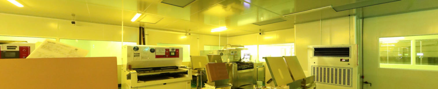
This is a crucial quality control step in the production process of PCBs. The electrical test is mainly conducted to check whether the electrical performance of the PCB meets the design requirements. It includes testing aspects such as the connectivity of the circuits (for example, checking for open circuits, that is, cases where the circuit is interrupted), insulation (such as whether there is a short - circuit between adjacent circuits), and electrical parameters (such as whether the characteristic impedance is within the specified range), etc. |
|
|
| |
|
|
|
|
| |
|
2. Importance of 100% Testing |
|
|
| |
|
Conducting 100% testing means that every PCB ready for shipment has to undergo a comprehensive check of its electrical performance. This is an important means to ensure product quality. Because even if only one PCB with electrical problems gets mixed into the shipment batch, it may cause malfunctions in the electronic devices using this PCB. For example, in the mass production of electronic products, if some PCBs have short - circuit problems and are not detected, when these PCBs are assembled into the products, they may damage other components upon startup and even pose safety risks. |
|
|
| |
|
|
|
|
| |
|
3. Enhancing Electrical Testing Efficiency |
|
|
| |
|
3.1 Adopt Automated Equipment
Automated testing can quickly and accurately evaluate many PCBs, reducing individual testing time significantly. Specialized instruments can perform multiple tests in seconds, while manual testing may take minutes.
3.2 Optimize the Testing Process
Sort testing items by the likelihood of PCB faults. Prioritize areas with historical issues, such as regions with frequent short-circuits, to detect defects early and reduce repeat tests.
3.3 Regularly Maintain and Calibrate Equipment
Keep equipment in optimal condition to avoid inaccurate results from failures or deviations, preventing repeated tests and saving time and manpower. |
|
|
| |
|
|
|
|
| |
|
4. Merits of AD255C Laminate |
|
|
| |
|
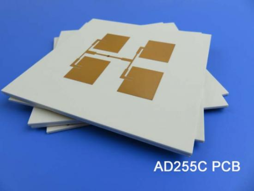
Before shipment, Bicheng Company's PCB products undergo 100% electrical testing. I was particularly impressed by the Rogers AD series PCBs. They feature low dielectric constants and low loss characteristics, which meet the demanding signal transmission requirements of high-frequency circuits. They are commonly used in fields such as wireless communication and radar. Next, let's discuss the advantages of the AD255C PCB. |
|
|
| |
|
 |
|
|
| |
|
|
|
|
| |
|
4.1 Low Loss |
|
|
| |
|
Made of highly engineered polytetrafluoroethylene and ceramic - filled composite materials. At 10 GHz, the loss factor of AD255C high frequency PCB is 0.0013, minimizing signal attenuation and energy loss. |
|
|
| |
|
|
|
|
| |
|
4.2 Stable Dielectric Constant |
|
|
| |
|
At 10 GHz and 23 °C, the dielectric constant is 2.55, with a tolerance of ±0.05, ensuring signal integrity and impedance for high - precision circuits. |
|
|
| |
|
|
|
|
| |
|
4.3 Good Insulation |
|
|
| |
|
The electrical strength is 911 V/mil, and the dielectric breakdown voltage is over 40 kV. It can bear high voltages, reducing the risks of leakage and short - circuit. |
|
|
| |
|
|
|
|
| |
|
4.4 Strong Anti - interference |
|
|
| |
|
It has excellent passive intermodulation (PIM) performance, with typical PIM values of - 159 / - 163 dBc, reducing signal interference. |
|
|
| |
|
|
|
|
| |
|
4.5 High Resistivities |
|
|
| |
|
The volume resistivity is 7.4x10⁸ MΩ·cm, and the surface resistivity is 3.6x10⁷ MΩ, preventing current leakage for circuit stability. |
|
|
| |
|
|
|
|
| |
|
4.6 Good Humidity |
|
|
| |
|
The moisture absorption rate is 0.03%, with minimal impact on the electrical performance in different humidities. |
|
|
| |
|
|
|
|
| |
|
4.7 Good Temperature |
|
|
| |
|
The decomposition temperature is over 500 °C, and it is stable from - 40 °C to + 85 °C, adaptable to complex environments. |
|
|
| |
|
|
|
|
| |
|
4-1. AD255C PCB Capability |
|
|
| |
|
PCB material: |
Glass-reinforced, PTFE based Composites |
Designation: |
AD255C |
Dielectric constant: |
2.55 (10 GHz) |
Dissipation Factor |
0.0013 (10 GHz) |
Layer count: |
Double Sided PCB, Multi-layer PCB, Hybrid PCB |
Copper weight: |
1oz (35µm), 2oz (70µm) |
Dielectric thickness: |
20mil (0.508mm), 30mil (0.762mm), 40mil (1.016mm), 60mil (1.524mm), 125mil (3.175mm) |
PCB size: |
≤400mm X 500mm |
Solder mask: |
Green, Black, Blue, Yellow, Red, Purple etc. |
Surface Finish: |
Immersion gold, Hot air soldering level (HASL), Immersion silver, Immersion tin, OSP, Pure gold plated, ENEPIG, Bare copper, etc.. |
|
|
|
| |
|
|
|
|
| |
|
5. Summary |
|
|
| |
|
In the field of high - frequency PCBs, electrical testing is the anchor of quality. It strictly controls the circuit performance, prevents signal distortion and interference, and enables the excellent performance of high - frequency electronic devices. |
|
|
| |
|
|
|
|
| |
|
Founded in 2003, Shenzhen Bicheng Electronics Technology Co., Ltd is an established high frequency PCB supplier and exporter in Shenzhen, China, serving customers worldwide.
We are devoted to delivering high-frequency PCB products and solutions of the highest quality, along with customized service. Feel free to consult and contant at any time !
Visit https://www.bicheng-enterprise.com to learn more.
Unlock its full potential by contacting Vicky at v.xie@bichengpcb.com. |
|
|
| |
|
|
|
| |
|
|
|
| |
|
|
|
| |
|
|
|
| |
|
|
|
| |
|
|
|
|
|