| |
 |
| |
|
|
|
|
|
| |
|
What is Coefficient of Thermal Expansion in High Frequency PCB? |
|
|
|
| |
|
1.The Overview of the coefficient of thermal expansion |
|
|
|
| |
|
The coefficient of thermal expansion (CTE), known as the "invisible killer" in high-frequency PCB design, is crucial for printed circuit boards. High-frequency PCBs are vital for electronic devices requiring high signal transmission quality, as the CTE measures how much a material's volume or length changes with temperature fluctuations, directly affecting circuit performance and reliability. |
|
|
| |
|
|
|
|
| |
|
2.Material Selection and CTE in High-Frequency PCBs |
|
|
| |
|
A low CTE reduces thermal stress, minimizes solder joint and connector failures, and enhances overall reliability. In temperature-fluctuating environments, low CTE materials provide greater dimensional stability. Although a low CTE is generally beneficial, multiple performance indicators such as dielectric constant, loss, and cost must be considered when selecting materials. Different applications have varied requirements. And a moderate CTE may better suit specific designs.
Among the various PCBls, Rogers RO4350B is highly recommended for its low and relatively suitable coefficient of thermal expansion. It exhibits excellent thermal stability with a coefficient of thermal expansion of 10 ppm/°C along the X-axis, 12 ppm/°C along the Y-axis, and 32 ppm/°C along the Z-axis, within the temperature range of -55°C to 288°C.
|
|
|
| |
|
|
|
|
| |
|
3.Rogers RO4350B Materials Uniting Performance and Compliance |
|
|
| |
|
Rogers RO4350B materials are proprietary woven glass-reinforced hydrocarbon/ceramics, offering electrical performance comparable to PTFE/woven glass while maintaining the manufacturability of epoxy/glass. It is worth mentioning that RO4350B™ laminates employ RoHS-compliant flame-retardant technology, making them suitable for applications that require UL 94V-0 certification. Additionally, these materials meet the IPC4103 standards. |
|
|
| |
|
|
|
|
| |
|
3-1.Rogers RO4350B |
|
|
| |
|
 |
|
|
| |
|
|
|
|
| |
|
3.1 Cost-Effective Performance of RO4350B Laminates |
|
|
| |
|
RO4350B laminates offer precise control over the dielectric constant (Dk) while ensuring low loss, all using the same processing methods as standard epoxy/glass. Priced considerably lower than traditional microwave laminates, RO4350B does not require the special through-hole treatments or handling procedures needed for PTFE-based materials. |
|
|
| |
|
|
|
|
| |
|
3.2 The Features of Rogers RO4350B |
|
|
| |
|
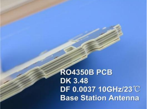
Dielectric Constant of 3.48 +/- 0.05
Dissipation factor of 0.0037 at 10 GHz
Favorable Thermal Conductivity of 0.69 W/m/°K
High glass transition temperature (Tg) of more than 280°C
Low water absorption rate of 0.05% |
|
|
| |
|
|
|
|
| |
|
3-2. Basic Specifications of Rogers RO4350B Series
Standard Thicknesses(RO4350B) |
0.004" (0.10mm) +/- 0.0007"
0.0066" (0.17mm) +/- 0.0007"
0.010" (0.25mm) +/- 0.0010"
0.020" (0.51mm) +/- 0.0015"
0.030" (0.76mm) +/- 0.0020"
0.060" (1.52mm) +/- 0.0040"
*Additional non - standard thicknesses available from 0.0066" - 0.060" in varying increments |
Standard Panel Sizes |
24" X 18" (610 X 457 mm)
24" X 21" (610 X 533 mm)
24" X 36" (610 X 915 mm)
48" X 36" (1219 X 915 mm)
*Additional panel sizes available |
Standard Claddings |
Electrodeposited Copper Foil
½ oz. (18μm) HH/HH
1 oz. (35μm) H1/H1
*Additional cladding weights available |
|
|
|
| |
|
|
|
|
| |
|
3.3 The Benefits of Rogers RO4350B |
|
|
| |
|
Cost-Effective: Processes like FR-4 offer lower fabrication costs.
Competitive Pricing: Affordably priced for a range of applications.
Outstanding Dimensional Stability: Maintains excellent stability under varying conditions. |
|
|
| |
|
|
|
|
| |
|
3.4 The Typical Applications of Rogers RO4350B |
|
|
| |
|
• Cellular Base Station Antennas and Power Amplifiers
• RF Identification Tags
• Automotive Radar and Sensors
• LNB’s for Direct Broadcast Satellites |
|
|
| |
|
|
|
|
| |
|
4. Signal Integrity and CTE |
|
|
| |
|
Signal integrity is a crucial factor in high-frequency PCB design. If a material's thermal expansion characteristics are not properly managed, it may lead to signal delays, distortion, or even loss, severely affecting the functionality of electronic devices. |
|
|
| |
|
|
|
|
| |
|
5. Optimizing Design to Enhance Reliability |
|
|
| |
|
ITo address the challenges of thermal expansion in high-frequency PCBs, designers can implement various strategies, such as choosing materials with low CTEs and optimizing circuit layouts to reduce thermal stress. Through these strategies, engineers can effectively enhance PCB performance and reliability, laying a solid foundation for the success of the final product. |
|
|
| |
|
|
|
|
| |
|
6. Conclusion |
|
|
| |
|
In the intricate realm of high-frequency PCBs, the coefficient of thermal expansion serves as a vital conductor,significantly influencing PCB performance.Mastering the CTE enables designers to navigate the challenges and opportunities of high-frequency PCBs, ensuring successful designs and efficient product performance. |
|
|
| |
|
|
|
|
| |
|
|
|
|
| |
|
|
|
|
| |
|
|
|
| |
|
|
|
| |
|
|
|
|
|