| |
 |
| |
|
|
|
|
|
| |
|
What is Arc Resistance in High Frequency PCB ? |
|
|
|
| |
|
1. Significance of Arc Resistance |
|
|
|
| |
|
IThe question "What is Arc Resistance in high-frequency PCB?" delves into the heart of the electronics industry. Arc resistance, in simple terms, is the ability of a PCB to resist arc discharge during high-frequency signal transmission, which is crucial for the stability and safety of high-speed signal processing. It ensures that signals are transmitted without interference and prevents circuit damage caused by arc discharge. In high-frequency applications such as 5G and IoT, the importance of arc resistance cannot be overstated, as it directly affects the overall performance, long-term stability, and lifespan of the equipment, serving as a key metric for assessing the quality of high-frequency PCBs. |
|
|
| |
|
|
|
|
| |
|
2. Influencing Factors |
|
|
| |
|
Material selection, manufacturing processes, and design layouts are key factors that influence the arc resistance of high-frequency PCBs. Suitable materials, precise processes, and optimized designs can significantly enhance arc resistance. |
|
|
| |
|
|
|
|
| |
|
3. Improvement Measures |
|
|
| |
|
3.1 Material Upgrade Utilizing materials with higher dielectric constants and lower loss tangents can more effectively resist arc discharge during high-frequency signal transmission, thereby increasing arc resistance.3.2 Process Optimization Through refined manufacturing processes, such as laser drilling and high-precision circuit pattern creation, defects and imperfections within the PCB can be minimized, thereby enhancing arc resistance. 3.3 Design Optimization In PCB design, proper layout and routing are essential. By optimizing circuit traces, reducing crossings and overlaps, the risk of arc discharge can be lowered, thus improving arc resistance. 3.4 Quality Control Implementing rigorous quality control measures during production ensures that each PCB meets design specifications, thereby maintaining the stability of arc resistance.
|
|
|
| |
|
|
|
|
| |
|
4. Superiorities of Taconic RF - 60A PCB |
|
|
| |
|
When it comes to the arc resistance in high-frequency PCBs, I can't help but think of Taconic RF - 60A laminate. The following is a detailed description and data support for the significant advantages of Taconic RF - 60A PCB substrate. |
|
|
| |
|
|
|
|
| |
|
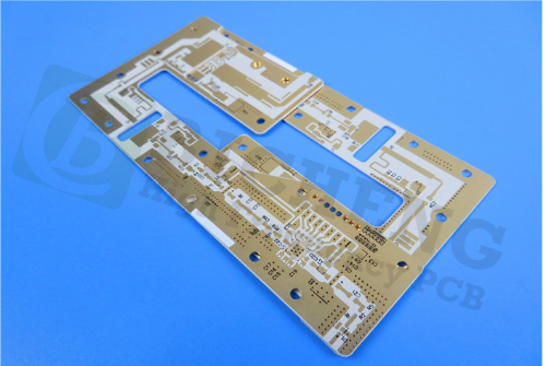
4-1. Taconic RF - 60A PCB |
|
|
| |
|
 |
|
|
| |
|
|
|
|
| |
|
4.1 High Arc Resistance Value |
|
|
| |
|
According to IPC - TM - 650, Taconic RF - 60A's arc resistance can reach 193s. For ordinary FR - 4, the standard is ≥60s (usually >100s in practice) at 12500V/10mA. So, Taconic RF - 60A PCB shows excellent performance. |
|
|
| |
|
|
|
|
| |
|
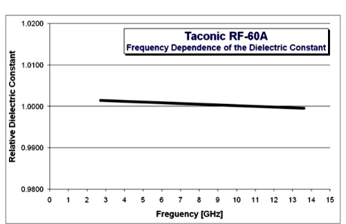
4.2 Stable Dielectric Constant |
|
|
| |
|
Its dielectric constant is ~6.15, stable in a wide frequency range. Stable dielectric helps reduce signal distortion & loss, lowering arc risk. In high - freq. circuits, it makes electric field distribution uniform, enhancing arc resistance. For example, in some comm. devices, using it can prevent signal reflection/scattering due to unstable dielectric, reducing arc chances. |
|
|
| |
|
 |
|
|
| |
|
|
|
|
| |
|
4.3 Low Water Absorption |
|
|
| |
|
The water absorption rate is <0.02%. This allows it to maintain good insulation & electrical properties in humid conditions. Moisture intrusion may degrade PCB insulation and increase arc risk. But Taconic RF - 60A laminate 's low water absorption ensures stable arc resistance. |
|
|
| |
|
|
|
|
| |
|
4.4 Extraordinary Inter - layer Bonding Strength |
|
|
| |
|
It has strong inter - layer bonding to prevent separation & blistering. When an arc occurs, this strength ensures PCB structure integrity, stopping arc spread along layers, further improving arc resistance. |
|
|
| |
|
|
|
|
| |
|
4.5 Low Z - axis Expansion Coefficient |
|
|
| |
|
The Z - axis expansion coefficient is only 69ppm/℃. Temperature changes won't cause much vertical expansion. Smaller Z - axis expansion helps maintain dimensional stability and reduce thermal - stress - induced arcs. In aerospace, automotive electronics, etc., it ensures reliable arc resistance. |
|
|
| |
|
|
|
|
| |
|
5. RF-60A PCB Capabilities |
|
|
| |
|
PCB Material: |
Organic-ceramic Woven Fiberglass Reinforced Laminates |
Designation: |
RF-60A |
Dielectric constant: |
6.15 ±0.25 |
Dissipation Factor |
DF 0.0038@10 GHz |
Thermal Conductivity |
0.4 W/MK |
Layer count: |
Double Layer, Multilayer, Hybrid PCB |
Copper weight: |
0.5oz (17 µm), 1oz (35µm), 2oz (70µm) |
PCB thickness: |
10mil (0.254mm), 25mil (0.635mm), 31mil (0.787mm), 50mil (1.27mm), 60mil (1.524mm), 125mil (3.175mm) |
PCB size: |
≤400mm X 500mm |
Solder mask: |
Green, Black, Blue, Yellow, Red etc. |
Surface finish: |
Bare copper, HASL, ENIG, OSP, Immersion tin etc.. |
|
|
|
| |
|
|
|
|
| |
|
6. Conclusion |
|
|
| |
|
Arc resistance is an indispensable performance indicator for high-frequency PCBs. Through material upgrades, process optimization, design enhancements, and quality control measures, the arc resistance of high-frequency PCBs can be significantly improved, better meeting the demands of future high-frequency applications. |
|
|
| |
|
|
|
|
| |
|
Founded in 2003, Shenzhen Bicheng Electronics Technology Co., Ltd is an established high frequency PCB supplier and exporter in Shenzhen, China, serving customers worldwide.
We are devoted to delivering high-frequency PCB products and solutions of the highest quality, along with customized service. Feel free to consult and contant at any time !
Visit https://www.bicheng-enterprise.com to learn more.
Unlock its full potential by contacting Vicky at v.xie@bichengpcb.com. |
|
|
| |
|
|
|
|
| |
|
|
|
|
| |
|
|
|
|
| |
|
|
|
| |
|
|
|
| |
|
|
|
|
|