| |
|
|
|
|
|
|
|
|
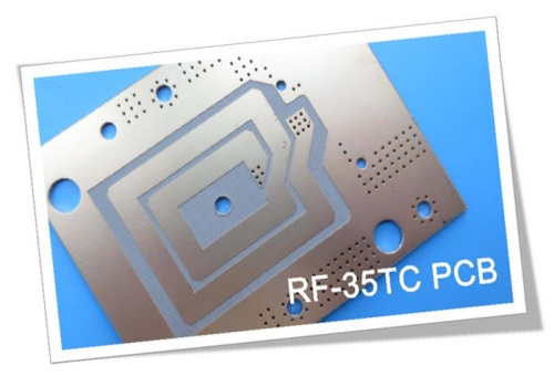
Taconic RF-35TC High Frequency PCB With 10mil, 20mil, 30mil and 60mil Thick Coating Immersion Gold and Immersion Silver |
|
|
|
|
|
(As PCBs are custom - produced goods, the picture and parameters shown are only intended for reference.) |
|
|
|
|
|
Hello Everyone,
We are pleased to introduce our new high-frequency PCB, designed with RF-35TC from Taconic. RF-35TC is a high-performance material composed of a PTFE (Polytetrafluoroethylene) base, ceramic fillers, and fiberglass reinforcement. This combination ensures superior performance for high-frequency applications. |
|
|
|
|
|
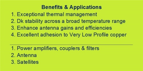
First, let’s examine some of its standout benefits. |
|
|
|
|
|
|
|
|
Exceptional Thermal Management
RF-35TC excels in thermal management, offering superior heat dissipation performance. As a thermally conductive, low-loss laminate, it is ideally suited for high-power applications. Heat is efficiently dissipated away from both the transmission lines on the PCB and surface-mounted components, such as capacitors.
Additionally, RF-35TC maintains stable dielectric constant (Dk) across a broad temperature range, enhancing antenna gains and efficiencies. Its excellent bonding with low-profile copper further reduces insertion loss, making it a top choice for high-performance designs.
Key Applications
Let’s take a closer look at its primary applications:
1. Power Amplifiers: With an extremely low dissipation factor (Df) of 0.0011 and high thermal conductivity, RF-35TC is particularly well-suited for power amplifier applications.
2. Couplers: Its low Z-axis coefficient of thermal expansion (CTE) and temperature-stable Dk make it critical for both narrow and broadband overlay couplers.
3. Filters: The low X and Y-axis CTE values ensure precise maintenance of critical distances between trace elements in printed filters.
Beyond these, RF-35TC is also widely used in antennas, satellite equipment, and other high-frequency applications.
Now that we’ve explored the material’s advantages and applications, let’s dive into our PCB manufacturing capabilities. |
|
|
|
|
Our PCB Capability (RF-35TC) |
|
|
PCB Material: |
PTFE based ceramic filled fiberglass substrate |
Designator: |
RF-35TC |
Dielectric constant @ 10GHz: |
3.50 |
|
|
Layer count: |
1 Layer, 2 Layer, Multilayer, Hybrid type |
Copper weight: |
0.5oz, 1oz, 2oz |
PCB thickness: |
0.3mm, 0.6mm, 0.8mm, 1.6mm |
|
(10mil, 20mil, 30mil, 60mil substrate) |
Solder mask: |
Green, Red, Black, White, Blue etc. |
PCB size: |
≤400mm X 500mm |
Surface finish: |
Bare copper, HASL, ENIG, Immersion tin etc. |
|
|
|
|
|
|
|
|
Currently, our company offers a range of PCB types, including single-sided, double-sided, multi-layer, and hybrid PCBs.
Copper Thickness: Primarily available in 1 oz and 2 oz.
Thickness Options: Various thicknesses are offered based on usage, such as 0.3 mm, 0.6 mm, 0.8 mm, and 1.6 mm.
Solder Mask Colors: Available in green, red, black, white, blue, and more.
Maximum PCB Size: Up to 400 x 500 mm.
Surface Finishes: Options include bare copper, hot air leveling, immersion gold, and immersion tin. |
|
|
|
|
|
 |
|
|
|
|
|
The standard colors for RF-35TC PCBs are brown and grey.
Our company specializes in prototypes, small batches, and mass production. If you have any questions, please don't hesitate to reach out.
Thank you for your attention! |
|
|
|
|
|
Appendix: Data Sheet RF-35TC |
|
|
RF-35TC TYPICAL VALUES |
Property |
Test Method |
Unit |
Value |
Unit |
Value |
DK @10 GHz |
IPC-650 2.5.5.5.1(modified) |
|
3.5 |
|
3.5 |
Tck(-30 to 120℃) |
IPC-650 2.5.5.5.1(modified) |
ppm |
24 |
ppm |
24 |
Df @10 GHz |
IPC-650 2.5.5.5.1(modified) |
|
0.0011 |
|
0.0011 |
Dielectric Breakdown |
IPC-650 2.5.6(in-Plane,Two Pins in Oil) |
kV |
56.7 |
kV |
56.7 |
Dielectric Strength |
ASTM D 149(Through Plane) |
V/mil |
570 |
V/mm |
22,441 |
Arc Resistance |
IPC-650 2.5.1 |
Seconds |
304 |
Seconds |
304 |
Moisture Absorption |
IPC-650 2.6.2.1 |
% |
0.05 |
% |
0.05 |
Flexural Strength(MD) |
ASTM D 790/IPC-650 2.4.4 |
psi |
12,900 |
N/mm2 |
88.94 |
Flexural Strength(CD) |
ASTM D 790/IPC-650 2.4.4 |
psi |
11,700 |
N/mm2 |
80.67 |
Tensile Strength(MD) |
ASTM D 3039/IPC-TM-650 2.4.19 |
psi |
9,020 |
N/mm2 |
62.19 |
Tensile Strength(CD) |
ASTM D 3039/IPC-TM-650 2.4.19 |
psi |
7,740 |
N/mm2 |
53.37 |
Elongation at Break(MD) |
ASTM D 3039/IPC-TM-650 2.4.19 |
% |
1.89 |
N/mm |
1.89 |
Elongation at Break(CD) |
ASTM D 3039/IPC-TM-650 2.4.19 |
% |
1.7 |
% |
1.7 |
Young's Modulus(MD) |
ASTM D 3039/IPC-TM-650 2.4.19 |
psi |
667,000 |
N/mm2 |
4,599 |
Young's Modulus(CD) |
ASTM D 3039/IPC-TM-650 2.4.19 |
psi |
637,000 |
N/mm2 |
4,392 |
Poisson's Ratio(MD) |
ASTM D 3039/IPC-TM-650 2.4.19 |
|
0.18 |
|
0.18 |
Poisson's Ratio(CD) |
ASTM D 3039/IPC-TM-650 2.4.19 |
|
0.23 |
|
0.18 |
Compressive Modulus |
ASTM D 695(23℃) |
psi |
560,000 |
N/mm2 |
3,861 |
Flexural Strength(MD) |
ASTM D 790/IPC-650 2.4.4 |
psi |
1.46 x 10⁶ |
N/mm2 |
10,309 |
Flexural Strength(CD) |
ASTM D 790/IPC-650 2.4.4 |
psi |
1.50 x 10⁶ |
N/mm2 |
10,076 |
Peel Stength(½ oz.CVH) |
IPC-650 2.4.8(Thermal Stress.) |
Ibs./inch |
7 |
g/cm3 |
1.25 |
Thermal Conductivity(Unclad,125℃) |
ASTM F433(Guarded Heat Flow) |
W/(mK) |
0.6 |
W/(mK) |
0.6 |
Thermal Conductivity(C1/C1,125℃) |
ASTM F433(Guarded Heat Flow) |
W/(mK) |
0.92 |
W/(mK) |
0.92 |
Thermal Conductivity(CH/CH,125℃) |
ASTM F433(Guarded Heat Flow) |
W/(mK) |
0.87 |
W/(mK) |
0.87 |
Dimensional Stability(MD) |
IPC-650-2.4.39 Sec.5.4(After Etch) |
mils/in. |
0.23 |
mm/M |
0.23 |
Dimensional Stability(CD) |
IPC-650-2.4.39 Sec.5.4(After Etch) |
mils/in. |
0.64 |
mm/M |
0.64 |
Dimensional Stability(MD) |
IPC-650-2.4.39 Sec.5.5(Thermal Stress.) |
mils/in. |
-0.04 |
mm/M |
-0.04 |
Dimensional Stability(CD) |
IPC-650-2.4.39 Sec.5.5(Thermal Stress.) |
mils/in. |
0.46 |
mm/M |
0.46 |
Surface Resistivity |
IPC-650 2.5.17.1(after elevated temp.) |
Mohms |
8.33 x 10⁷ |
Mohms |
8.33 x 10⁷ |
Surface Resistivity |
IPC-650 2.5.17.1(after humidity) |
Mohms |
6.42 x 10⁷ |
Mohms |
6.42 x 10⁷ |
Volume Resistivity |
IPC-650 2.5.17.1(after elevated temp.) |
Mohms/cm |
5.19 x 10⁸ |
Mohms/cm |
5.19 x 10⁸ |
Volume Resistivity |
IPC-650 2.5.17.1(after humidity) |
Mohms/cm |
2.91 x 10⁸ |
Mohms/cm |
2.91 x 10⁸ |
CTE(X axis)(25-260℃) |
IPC-650 2.4.41/ASTM D 3386 |
ppm/℃ |
11 |
ppm/℃ |
11 |
CTE(Y axis)(25-260℃) |
IPC-650 2.4.41/ASTM D 3386 |
ppm/℃ |
13 |
ppm/℃ |
13 |
CTE(Z axis)(25-260℃) |
IPC-650 2.4.41/ASTM D 3386 |
ppm/℃ |
34 |
ppm/℃ |
34 |
Density |
ASTM D 792 |
g/cm3 |
2.35 |
g/cm3 |
2.35 |
Hardness |
ASTM D 2240(Shore D) |
|
79.1 |
|
79.1 |
Strain at Break(MD) |
ASTM D 790/IPC-650 2.4.4 |
% |
0.014 |
% |
0.014 |
Strain at Break(CD) |
ASTM D 790/IPC-650 2.4.4 |
% |
0.013 |
% |
0.013 |
Specific Heat |
ASTM E 1269-05,E 967-08,E968-02 |
j/(g℃) |
0.94 |
j/(g℃) |
0.94 |
Td(2% Weight Loss) |
IPC-650 2.4.24.6/TGA |
oF |
788 |
℃ |
420 |
Td(5% Weight Loss) |
IPC-650 2.4.24.6/TGA |
oF |
817 |
℃ |
436 |
|
|
|
|
|
|
Hot Tags:
Taconic RF-35TC Price |
Taconic RF-35TC Thickness |
RF-35TC Material |
RF-35TC Loss Tangent |
RF-35TC Datasheet |
|
|
|
