| |
|
|
|
|
|
|
|
|
Taconic-RF-10-10mil-20mil-60mil-PCB-RF-10-High-Frequency-Printed-Circuit-Board-with-Low-Loss-and-High-DK |
|
|
(Printed Circuit Boards are custom-made products. The picture and parameters shown are for reference only.) |
|
|
|
|
|
Brief Introduction |
|
|
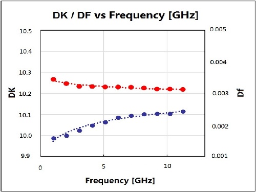
Taconic RF-10 PCBs represent an advanced composite material, masterfully combining ceramic - loaded PTFE with interwoven fiberglass. These remarkable laminates distinguish themselves by boasting a substantial dielectric constant of 10.2 at 10GHz and an incredibly low dissipation factor of 0.0025 at that same frequency. Through the integration of thin woven fiberglass reinforcement, Taconic RF- 10 printed circuit boards offer two significant advantages: reducing dielectric losses and increasing rigidity. This enhancement simplifies the handling process and improves dimensional stability, which is of utmost importance for multilayer circuit designs.
Engineered to address the need for affordable substrates in radio frequency (RF) applications, Taconic RF-10 high- frequency PCBs are the perfect solution for shrinking the size of RF components. They establish a robust connection with sleek, low - profile copper. When paired with the material's minimal dissipation and the utilization of ultra - smooth copper, Taconic RF-10 PCBs guarantee optimal insertion losses at elevated frequencies. At such frequencies, skin effect losses can severely affect performance, but RF- 10 laminate efficiently overcomes this challenge, enabling dependable and efficient operation. |
|
|
|
|
|
Features and Benefits |
|
|
- Excellent adhesion to smooth coppers
- Excellent dimensional stability
- Excellent price/performance ratio
- High thermal conductivity for enhanced thermal management
- High DK for RF circuit size reduction
- Low 0.0025 loss tangent @ 10 GHz
- Low X, Y, Z expansion
- Tight DK tolerance (10.2 +/-0.3)
|
|
|
|
|
|
 |
|
|
|
|
|
 |
|
|
|
|
|
Typical Applications |
|
|
- Aircraft Collision Avoidance Systems
- GPS Antennas
- Microstrip Patch Antennas
- Passive Components (filters, couplers, power dividers)
- Satellite Components
|
|
|
|
|
|
.jpg) |
|
|
|
|
|
Our PCB Capability (RF-10) |
|
|
PCB Capability (RF-10) |
PCB Material: |
Composites of Ceramic Filled PTFE and Woven Fiberglass |
Designation: |
RF-10 |
Dielectric constant: |
10.2 |
Dissipation Factor |
0.0025 10GHz |
Layer count: |
Double Sided PCB, Multilayer PCB, Hybrid PCB |
Copper weight: |
0.5oz (17 µm), 1oz (35µm), 2oz (70µm) |
PCB thickness: |
10mil (0.254mm), 20mil (0.508mm), 25mil (0.635mm), 60mil (1.524mm ), 125mil ( 3.175mm ) |
PCB size: |
≤400mm X 500mm |
Solder mask: |
Green, Black, Blue, Yellow, Red etc. |
Surface finish: |
Bare copper, HASL, ENIG, Immersion silver, Immersion tin, OSP, Pure gold, ENEPIG etc.. |
|
|
|
|
|
|
RF-10 Typical Values |
|
|
RF-10 Typical Values |
Property |
Test Method |
Unit |
Value |
Unit |
Value |
Dk @ 10 GHz |
IPC-650 2.5.5.5.1 Mod. |
|
10.2 ± 0.3 |
|
10.2 ± 0.3 |
Df @ 10 GHz |
IPC-650 2.5.5.5.1 Mod. |
|
0.0025 |
|
0.0025 |
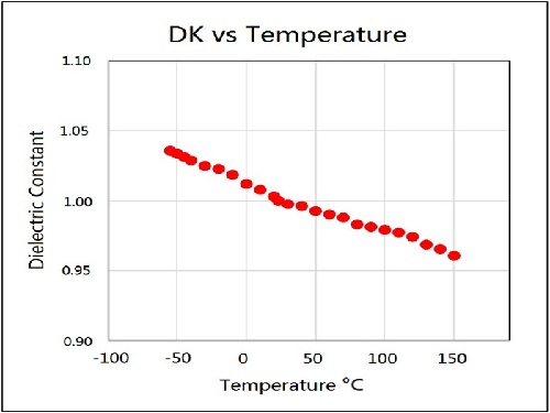
TcK† (-55 to 150 °C) |
IPC-650 2.5.5.6 |
ppm/°C |
-370 |
ppm/°C |
-370 |
Moisture Absorption |
IPC-650 2.6.2.1 |
% |
0.08 |
% |
0.08 |
Peel Strength (1 oz. RT copper) |
IPC-650 2.4.8 (solder) |
lbs/in |
10 |
N/mm |
1.7 |
Volume Resistivity |
IPC-650 2.5.17.1 |
Mohm/cm |
6.0 x 10⁷ |
Mohm/cm |
6.0 x 10⁷ |
Surface Resistivity |
IPC-650 2.5.17.1 |
Mohm |
1.0 x 10⁸ |
Mohm |
1.0 x 10⁸ |
Flexural Strength (MD) |
IPC - 650 - 2.4.4 |
psi |
14,000 |
N/mm2 |
96.53 |
Flexural Strength (CD) |
IPC - 650 - 2.4.4 |
psi |
10,000 |
N/mm2 |
68.95 |
Tensile Strength (MD) |
IPC - 650 - 2.4.19 |
psi |
8,900 |
N/mm2 |
62.57 |
Tensile Strength (CD) |
IPC - 650 - 2.4.19 |
psi |
5,300 |
N/mm2 |
37.26 |
Dimensional Stability |
IPC-650 2.4.39 (After Etch) |
% (25 mil-MD) |
-0.0032 |
% (25 mil-CD) |
-0.0239 |
Dimensional Stability |
IPC-650 2.4.39 (After Bake) |
% (25 mil-MD) |
-0.0215 |
% (25 mil-CD) |
-0.0529 |
Dimensional Stability |
IPC-650 2.4.39 (After Stress) |
% (25 mil-MD) |
-0.0301 |
% (25 mil-CD) |
-0.0653 |
Dimensional Stability |
IPC-650 2.4.39 (After Etch) |
% (60 mil-MD) |
-0.0027 |
% (60 mil-CD) |
-0.0142 |
Dimensional Stability |
IPC-650 2.4.39 (After Bake) |
% (60 mil-MD) |
-0.1500 |
% (60 mil-CD) |
-0.0326 |
Dimensional Stability |
IPC-650 2.4.39 (After Stress) |
% (60 mil-MD) |
-0.0167 |
% (60 mil-CD) |
-0.0377 |
Density (Specific Gravity) |
IPC-650-2.3.5 |
g/cm3 |
2.77 |
g/cm3 |
2.77 |
Specific Heat |
IPC-650-2.4.50 |
J/g°C |
0.9 |
J/g°C |
0.9 |
Thermal Conductivity (Unclad) |
IPC-650-2.4.50 |
W/M*K |
0.85 |
W/M*K |
0.85 |
CTE (X -Y axis) (50 to 150 °C) |
IPC-650 2.4.41 |
ppm/°C |
16-20 |
ppm/°C |
16-20 |
CTE (Z axis) (50 to 150 °C) |
IPC-650 2.4.41 |
ppm/°C |
25 |
ppm/°C |
25 |
Flammability Rating |
Internal |
|
V-0 |
|
V-0 |
|
|
|
|
|
|
|
|
|
|
|
|
|
|
|
|
|
|
|
|
|
Hot Tags:
Taconic RF-10 PCB |
Taconic RF-10 Circuit Board |
Taconic Low Loss PCB |
10mil 20mil 60mil RF-10 PCB |
RF-10 High Frequency PCB |
|
|
|
