| |
|
|
|
|
|
|
|
|
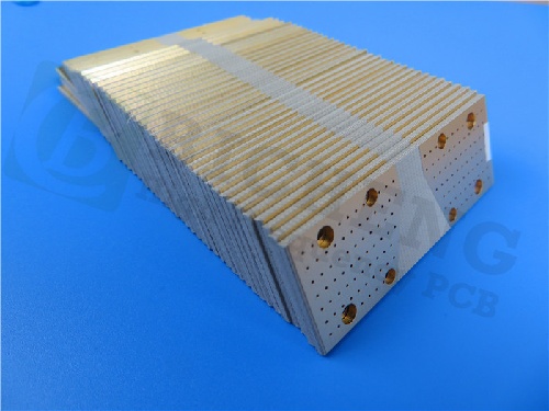
Rogers RT/duroid 6035 PCB Built On Dual Layer 30mil Core With Immersion Gold for Power Dividers |
|
|
(Printed Circuit Boards are custom-made products. The picture and parameters shown are for reference only.) |
|
|
|
|
|
Rogers RT/duroid 6035HTC high - frequency circuit materials, which are ceramic - filled PTFE composites, are made for high - power RF and microwave applications. They possess a thermal conductivity that is approximately 2.4 times higher than the standard RT/duroid 6000 products. The copper foil (electrodeposited and reverse - treated) of these laminates shows excellent long - term thermal stability. Therefore, RT/duroid 6035HTC substrates are an ideal choice for high - power applications. |
|
|
 |
|
|
|
|
|
Features/Benefits:
1.High Thermal conductivity Improved dielectric heat dissipation enables lower operating temperatures for high power applications
2.Low loss tangent Excellent high frequency performance
3.Thermally stable low profile and reverse treat copper foil Lower insertion loss and excellent thermal stability of traces
4.Advanced filler system Improved drill ability and extended tool life compared to alumina containing circuit materials |
|
|
|
|
|
Typical applications:
1.High Power RF and Microwave Amplifiers
2.Power amplifiers, Couplers, Filters
3.Combiners, Power Dividers |
|
|
|
|
PCB Capability(RT/duroid 6035HTC) |
|
PCB Capability (RT/duroid 6035HTC) |
PCB Material: |
Ceramic-filled PTFE composites |
Designation: |
RT/duroid 6035HTC |
Dielectric constant: |
3.50±0.05 |
Layer count: |
Double Layer, Multilayer, Hybrid PCB |
Copper weight: |
0.5oz (17 µm), 1oz (35µm), 2oz (70µm) |
Laminate thickness: |
10mil (0.254mm), 20mil(0.508mm), 30mil (0.762mm), 60mil(1.524mm) |
PCB size: |
≤400mm X 500mm |
Solder mask: |
Green, Black, Blue, Yellow, Red etc. |
Surface finish: |
Bare copper, HASL, ENIG, Immersion silver, Immersion tin, OSP etc.. |
|
|
|
|
RT/duroid 6035HTC Data Sheet |
|
Property |
Typical Value RT/duroid 6035HTC |
Direction |
Unit |
Condition |
Test Method |
Dielectric Constant, εr Process |
3.50 ± 0.05 |
Z |
- |
10 GHz/23°C |
IPC-TM-650 2.5.5.5 Clamped Stripline |
Dielectric Constant, εr
Design |
3.6 |
Z |
- |
8 GHz - 40 GHz |
Differential Phase Length Method |
Dissipation Factor, |
0.0013 |
Z |
- |
10 GHz/23°C |
IPC-TM-650, 2.5.5.5 |
Thermal Coefficient of εr |
-66 |
Z |
ppm/°C |
-50°C to 150°C |
mod IPC-TM-650, 2.5.5.5 |
Dielectric Strength |
835 |
- |
V/Mil |
15 mil thickness |
IPC-TM-650, 2.5.6.2 |
Breakdown Voltage |
12.59 |
- |
kV |
15 mil thickness |
IPC-TM-650, 2.5.6 |
Volume Resistivity |
108 |
- |
MΩ•cm |
COND A |
IPC-TM-650, 2.5.17.1 |
Surface Resistivity |
108 |
- |
MΩ |
COND A |
IPC-TM-650, 2.5.17.1 |
Tensile Modulus |
329
244 |
MD
CMD |
kpsi |
40 hrs @ 23°C/50RH |
ASTM D638 |
Dimensional Stability |
-0.11
-0.08 |
CMD
MD |
mm/m
(mils/inch) |
0.030” 1 oz EDC foil
Thickness
after etch +E4/105 |
IPC-TM-650, 2.4.39A |
Coefficient of Thermal
Expansion (-55 to 288 °C) |
19 |
X |
ppm/°C |
23°C/50% RH |
IPC-TM-650 2.4.41 |
|
19 |
Y |
|
|
|
|
39 |
Z |
|
|
|
Thermal Conductivity |
1.44 |
- |
W/m/K |
80°C |
ASTM C518 |
Moisture Absorption |
0.06 |
- |
% |
D24/23 |
IPC-TM-650 2.6.2.1 ASTM D570 |
Density |
2.2 |
- |
gm/cm3 |
23°C |
ASTM D-792 |
Copper Peel Strength |
7.9 |
- |
pli |
20 sec.@ 288°C |
IPC-TM-650 2.4.8 |
Flammability |
V-0 |
- |
- |
- |
UL 94 |
Lead-Free Process
Compatible |
YES |
|
|
|
|
|
|
|
|
|
|
|
|
|
|
|
|
Hot Tags:
RT/duroid-6035HTC Datasheet |
10mil RT/duroid 6035HTC Thickness |
Rogers RT/duroid 6035HTC PCB |
RT/duroid 6035HTC Online Purchase |
RT/duroid 6035HTC Substrate |
|
|
|
