| |
|
|
|
|
|
|
|
|
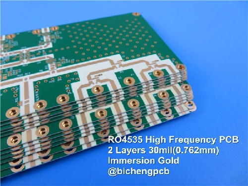
Rogers RO4535 High Frequency PCB 2-Layer 30mil 0.762mm Antenna Circuit Board with Immersion Gold |
|
|
(Printed Circuit Boards are custom-made products. The picture and parameters shown are for reference only.) |
|
|
|
|
|
General Description |
|
|
Rogers RO4535 PCB delivers high-frequency antenna solutions through its 30-mil substrate construction, starting with 0.5-ounce copper that's processed to achieve 1-ounce final thickness. RO4535 PCB features a green solder mask on its top layer and full-bottom-side immersion gold plating, ensuring corrosion-resistant surface performance.
Rogers RO4535 PCB meets IPC Class 2 requirements as a double-layer design, maintaining rigorous quality control through 100% electrical testing via flying probe or custom fixtures. Engineered for reliability, RO4535 laminate guarantees functional integrity from production to end-user delivery.
Optimized for RF applications, Rogers RO4535 PCB combines its enhanced copper weight and gold-plated bottom layer to support stable signal transmission in microwave systems. With its tested durability and standardized manufacturing, RO4535 substrate serves as a robust foundation for 5G infrastructure, IoT devices, and aerospace communication platforms. |
|
|
|
|
|
 |
|
|
|
|
|
PCB Specifications |
|
|
PCB SIZE |
75 x 170mm=1up |
BOARD TYPE |
Double sided PCB |
Number of Layers |
2 layers |
Surface Mount Components |
YES |
Through Hole Components |
NO |
LAYER STACKUP |
copper ------- 17um(0.5 oz)+plate TOP layer |
|
Rogers RO4535 0.762mm |
|
copper ------- 17um(0.5 oz) + plate BOT Layer |
TECHNOLOGY |
|
Minimum Trace and Space: |
4 mil / 4 mil |
Minimum / Maximum Holes: |
0.3 mm / 3.0 mm |
Number of Different Holes: |
8 |
Number of Drill Holes: |
358 |
Number of Milled Slots: |
0 |
Number of Internal Cutouts: |
0 |
Impedance Control: |
no |
Number of Gold finger: |
0 |
BOARD MATERIAL |
|
Glass Epoxy: |
Rogers RO4535 0.762mm |
Final foil external: |
1.0 oz |
Final foil internal: |
N/A |
Final height of PCB: |
0.8 mm ±0.1 |
PLATING AND COATING |
|
Surface Finish |
Immersion Gold, 37.8% |
Solder Mask Apply To: |
Top side |
Solder Mask Color: |
Green |
Solder Mask Type: |
LPI |
CONTOUR/CUTTING |
Routing |
MARKING |
|
Side of Component Legend |
Component Side |
Colour of Component Legend |
White |
Manufacturer Name or Logo: |
N/A |
VIA |
Plated through hole(PTH), minimum size 0.3mm. |
FLAMIBILITY RATING |
94V-0 |
DIMENSION TOLERANCE |
|
Outline dimension: |
0.0059" |
Board plating: |
0.0029" |
Drill tolerance: |
0.002" |
TEST |
100% Electrical Test prior shipment |
TYPE OF ARTWORK TO BE SUPPLIED |
email file, Gerber RS-274-X, PCBDOC etc |
SERVICE AREA |
Worldwide, Globally. |
|
|
|
|
|
|
Our Advantages |
|
|
1.Powerful PCB capabilities support your research and development, sales and marketing;
2.PCB Products and Manufacturing are certified by authorized organizations;
3.16000㎡ workshop with 30000㎡ output capability and 8000 types of PCB's per month;
4.Quick CADCAM checking and free PCB quotation;
5.No minimum order quantity. 1 piece is available;
6.A Team with passion, discipline, responsibility and honesty;
7.More than 19+ years of high frequency PCB experience;
8.Prototype PCB capability to Volume Production capability;
9.Delivery on time: >98%, Customer complaint rate: <1%
10.IPC Class 2 / IPC Class 3; |
|
|
|
|
|
Our PCB Capabilities(2022) |
|
|
Parameter |
Value |
Layer Counts |
1-32 |
Substrate Material |
RO4350B, RO4003C, RO4730G3, RO4360G2, RO4533, RO4534, RO4535, RO3003, RO3006, RO3010, RO3035, RO3203, RO3210; RT/Duriod 5880; RT/Duriod 5870, RT/Duriod 6002, RT/Duroid 6010, RT/duroid 6035HTC; TMM3, TMM4, TMM6, TMM10, TMM10i, TMM13i, Kappa 438; TLF-35; RF-35TC, RF-60A, RF-60TC, RF-35A2, RF-45, RF-10, TRF-45; TLX-0, TLX-6, TLX-7, TLX-8; TLX-9, TLY-3, TLY-5; PTFE F4B (DK2.2 DK2.65 DK2.85 DK2.94, DK3.0, DK3.2, DK3.38, DK3.5, DK4.0, DK4.4, DK6.15, DK10.2); AD450, AD600, AD1000, TC350; Nelco N4000, N9350, N9240; FR-4 ( High Tg S1000-2M, TU-872 SLK, TU-768, IT-180A etc.), FR-4 High CTI>600V; Polyimide, PET; Metal Core etc. |
Maximum Size |
Flying test: 900*600mm, Fixture test 460*380mm, No test 1100*600mm |
Board Outline Tolerance |
±0.0059" (0.15mm) |
PCB Thickness |
0.0157" - 0.3937" (0.40mm--10.00mm) |
Thickness Tolerance(T≥0.8mm) |
±8% |
Thickness Tolerance(t<0.8mm) |
±10% |
Insulation Layer Thickness |
0.00295" - 0.1969" (0.075mm--5.00mm) |
Minimum Track |
0.003" (0.075mm) |
Minimum Space |
0.003" (0.075mm) |
Outer Copper Thickness |
35µm--420µm (1oz-12oz) |
Inner Copper Thickness |
17µm--350µm (0.5oz - 10oz) |
Drill Hole(Mechanical) |
0.0059" - 0.25" (0.15mm--6.35mm) |
Finished Hole(Mechanical) |
0.0039"-0.248" (0.10mm--6.30mm) |
DiameterTolerance(Mechanical) |
0.00295" (0.075mm) |
Registration (Mechanical) |
0.00197" (0.05mm) |
Aspect Ratio |
12:1 |
Solder Mask Type |
LPI |
Min Soldermask Bridge |
0.00315" (0.08mm) |
Min Soldermask Clearance |
0.00197" (0.05mm) |
Plug via Diameter |
0.0098" - 0.0236" (0.25mm--0.60mm) |
Impedance Control Tolerance |
±10% |
Surface Finish |
HASL,HASL LF,ENIG,Immersion Tin,Immersion Silver, OSP, Gold Finger, Pure gold plated etc. |
|
|
|
|
|
Appendix: Typical Value of RO4535 |
|
Property |
RO4535 |
Direction |
Units |
Condition |
Test Method |
Dielectric Constant, er Process |
3.44 ± 0.08 |
Z |
- |
10 GHz/23℃ 2.5 GHz |
IPC-TM-650,2.5.5.5 |
Dissipation Factor |
0.0032 |
Z |
- |
2.5 GHz/23℃ |
IPC-TM-650, 2.5.5.5 |
|
0.0037 |
|
|
10 GHz/23℃ |
|
PIM (Typical) |
-157 |
- |
dBc |
Reflected 43 dBm swept tones |
Summitek 1900b PIM Analyzer |
Dielectric Strength |
>500 |
Z |
V/mil |
0.51 mm |
IPC-TM-650, 2.5.6.2 |
Dimensional Stability |
<0.5 |
X,Y |
mm/m (mils/inch) |
after etch |
IPC-TM-650, 2.4.39A |
Coefficient of Thermal Expansion |
16 |
X |
ppm/℃ |
-55 to 288℃ |
IPC-TM-650, 2.4.41 |
|
17 |
Y |
|
|
|
|
50 |
Z |
|
|
|
Thermal Conductivity |
0.6 |
- |
W/(m.K) |
80℃ |
ASTM C518 |
Moisture Absorption |
0.09 |
- |
% |
D48/50 |
IPC-TM-650, 2.6.2.1 ASTM D570 |
Tg |
>280 |
- |
℃ TMA |
A |
IPC-TM-650, 2.4.24.3 |
Density |
1.9 |
- |
gm/cm3 |
- |
ASTM D792 |
Copper Peel Strength |
5.1 (0.9) |
- |
lbs/in (N/mm) |
1 oz. EDC post solder float |
IPC-TM-650, 2.4.8 |
Flammability |
V-0 |
- |
- |
- |
UL 94 |
Lead-Free Process Compatible |
Yes |
- |
- |
- |
- |
|
|
|
|
|
|
|
|
|
|
|
|
Hot Tags:
Rogers 4535 Circuit Board |
RO4535 High Frequency Antenna PCB |
Double Sided Rogers 4535 PCB |
Rogers 4535 30 Mil PCB |
Rogers 4535 Antenna PCB |
|
|
|
