| |
|
|
|
|
|
|
|
|
Rogers RO3003 High Frequency Printed Circuit Board Rogers DK3.0 GPS Antenna RF PCB 10mil, 20mil, 30mil and 60mil Thick Coating Immersion Gold |
|
|
|
|
|
(As PCBs are custom - produced goods, the picture and parameters shown are only intended for reference.) |
|
|
|
|
|
Hello Everyone,
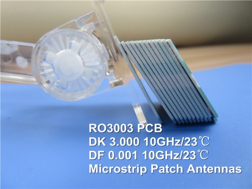
Today, we’re discussing RO3003 high-frequency PCBs. RO3003 high-frequency circuit laminates are ceramic-filled PTFE composites designed for commercial microwave and RF applications. A key characteristic of these laminates is their exceptional electrical performance, coupled with stable and consistent mechanical properties. This reliability enables our designers to create multi-layer board designs with confidence, avoiding issues like warpage and reliability concerns.
Now, let’s explore some additional features and applications. |
|
|
|
|
|
 |
|
|
|
|
|
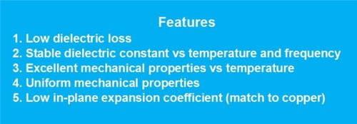
1. Low Dielectric Loss: With a dielectric factor (DF) of 0.001, RO3003 is suitable for applications up to 77 GHz.
2. Stable Dielectric Constant: Its dielectric constant remains stable across temperature and frequency, making it an ideal material for band-pass filters, microstrip patch antennas, and voltage-controlled oscillators.
3. Excellent Mechanical Properties: The laminate offers reliable performance in stripline and multi-layer board constructions, even at varying temperatures.
4. Uniform Mechanical Properties: Its consistent mechanical properties make it suitable for use in epoxy-glass multi-layer board hybrid designs. Low In-Plane
5. Expansion Coefficient: Matching the expansion coefficient of copper, it ensures more reliable surface-mounted assemblies, making it ideal for applications sensitive to temperature changes and providing excellent dimensional stability. |
|
|
|
|
Our PCB Capability (RO3003)) |
|
|
PCB Material: |
Ceramic-filled PTFE composite |
Designator: |
RO3003 |
Dielectric constant: |
3.0 ±0.04 (process) |
|
3.0 (design) |
Layer count: |
1 Layer, 2 Layer, Multilayer, Hybrid PCB |
Copper weight: |
0.5oz (17 µm), 1oz (35µm), 2oz (70µm) |
PCB thickness: |
10mil (0.254mm), 20mil (0.508mm) |
|
30mil (0.762mm), 60mil (1.524mm) |
PCB size: |
≤400mm X 500mm |
Solder mask: |
Green, Black, Blue, Yellow, Red etc. |
Surface finish: |
Bare copper, HASL, ENIG, OSP etc.. |
|
|
|
|
|
|
|
|
Rogers RO3003 high-frequency PCBs come in double-sided, multi-layer, and hybrid constructions. The copper thickness ranges from 0.5 oz to 2 oz, with board thicknesses available from 0.3 mm to 1.6 mm. The maximum dimensions are 400 mm by 500 mm, and surface finishes include bare copper, hot air leveling, immersion gold, and more. |
|
|
|
|
|
 |
|
|
|
|
|
Typical Applications
1. Automotive radar applications
2. GPS Antennas
3. Power amplifiers and antennas
4. Patch antennas for wireless communications
5. Direct broadcast satellite |
|
|
|
|
|
 |
|
|
|
|
|
The base color of RO3003 PCBs is white.
The manufacturing process for RO3003 high-frequency PCBs is similar to that of standard PTFE PCBs, making it well-suited for volume production and providing a competitive market advantage.
If you have any questions, please don’t hesitate to reach out.
Thank you for reading! |
|
|
|
|
|
Appendix: RO3003 Data Sheet |
|
|
RO3003 Typical Value |
Property |
RO3003 |
Direction |
Units |
Condition |
Test Method |
Electrical Properties |
|
|
|
|
|
Dielectric Constant,εProcess |
3.0±0.04 |
Z |
|
10 GHz/23℃ |
IPC-TM-650 2.5.5.5 Clamped Stripline |
Dielectric Constant,εDesign |
3 |
Z |
|
8GHz to 40 GHz |
Differential Phase Length Method |
Dissipation Factor,tanδ |
0.001 |
Z |
|
10 GHz/23℃ |
IPC-TM-650 2.5.5.5 |
Thermal Coefficient of ε |
-3 |
Z |
ppm/℃ |
10 GHz -50℃to 150℃ |
IPC-TM-650 2.5.5.5 |
Volume Resistivity |
107 |
|
MΩ.cm |
COND A |
IPC 2.5.17.1 |
Surface Resistivity |
107 |
|
MΩ |
COND A |
IPC 2.5.17.1 |
Thermal Properties |
|
|
|
|
|
Td |
500 |
|
℃ TGA |
|
ASTM D 3850 |
Coefficient of Thermal Expansion
(-55 to 288℃) |
17
16
25 |
X
Y
Z |
ppm/℃ |
23℃/50% RH |
IPC-TM-650 2.4.4.1 |
Thermal Conductivity |
0.5 |
|
W/M/K |
50℃ |
ASTM D 5470 |
Mechanical Properties |
|
|
|
|
|
Copper Peel Stength |
12.7 |
|
Ib/in. |
1oz,EDC After Solder Float |
IPC-TM 2.4.8 |
Young's Modulus |
930
823 |
X
Y |
MPa |
23℃ |
ASTM D 638 |
Dimensional Stability |
-0.06
0.07 |
X
Y |
mm/m |
COND A |
IPC-TM-650 2.2.4 |
Physical Properties |
|
|
|
|
|
Flammability |
V-0 |
|
|
|
UL 94 |
Moisture Absorption |
0.04 |
|
% |
D48/50 |
IPC-TM-650 2.6.2.1 |
Density |
2.1 |
|
gm/cm3 |
23℃ |
ASTM D 792 |
Specific Heat |
0.9 |
|
j/g/k |
|
Calculated |
Lead-free Process Compatible |
Yes |
|
|
|
|
|
|
|
Hot Tags:
RO3003 Dielectric Constant |
Rogers RO3003 Thickness |
Rogers RO3003 Material |
Rogers RO3003 Substrate |
RO3003 Loss Tangent |
|
|
|
