| |
|
|
|
|
|
|
|
|
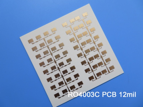
Rogers 4003C 12mil 0.305mm High Frequency Circuit Board for Antennas Immersion Gold |
|
|
(Printed Circuit Boards are custom-made products. The picture and parameters shown are for reference only.) |
|
|
|
|
|
RO4003C hydrocarbon ceramic laminates are designed to provide superior high frequency performance and enable low cost circuit fabrication. Once operational frequencies reach 500 MHz and above, the selection of laminates typically available to designers is significantly narrowed. The RO4003C material has the properties required by designers of RF microwave circuits, matching networks, and controlled impedance transmission lines. Due to its low dielectric loss, the RO4003C material can be utilized in many applications where higher operating frequencies restrict the use of conventional circuit board materials.
|
|
|
 |
|
|
RO4003C circuit board material boasts an exceptionally low temperature coefficient of dielectric constant, maintaining stability across a wide frequency range. Its CTE offers significant advantages to PCB designers, being comparable to copper's, thus ensuring excellent dimensional stability essential for multi-layer boards with mixed dielectrics. Furthermore, the low Z-axis CTE of RO4003C guarantees reliable plated through-holes even in applications involving severe thermal shock. With a Tg of over 280°C, its expansion properties remain consistent throughout the entire PCB processing temperature range.
|
|
|
RO4003C PCB Specifications |
|
|
Rogers 12mil 0.305mm RO4003C High Frequency PCB Double Sided RF PCB for Antennas |
|
|
PCB SIZE |
67 x 67mm=1up |
BOARD TYPE |
Double sided PCB |
Number of Layers |
2 layers |
Surface Mount Components |
YES |
Through Hole Components |
NO |
LAYER STACKUP |
copper ------- 35um(1 oz)+plate TOP layer |
RO4003C 0.305mm |
copper ------- 35um(1oz) + plate BOT Layer |
TECHNOLOGY |
|
Minimum Trace and Space: |
7.9 mil / 5.9 mil |
Minimum / Maximum Holes: |
0.4 mm / 0.4 mm |
Number of Different Holes: |
1 |
Number of Drill Holes: |
3 |
Number of Milled Slots: |
0 |
Number of Internal Cutouts: |
0 |
Impedance Control: |
no |
Number of Gold finger: |
0 |
BOARD MATERIAL |
|
Glass Epoxy: |
RO4003C Tg280℃, er<3.48, Rogers Corp. |
Final foil external: |
1.5 oz |
Final foil internal: |
N/A |
Final height of PCB: |
0.4 mm ±0.1 |
PLATING AND COATING |
|
Surface Finish |
Immersion gold, 18% |
Solder Mask Apply To: |
N/A |
Solder Mask Color: |
N/A |
Solder Mask Type: |
N/A |
CONTOUR/CUTTING |
Routing |
MARKING |
|
Side of Component Legend |
N/A |
Colour of Component Legend |
N/A |
Manufacturer Name or Logo: |
N/A |
VIA |
Plated through hole(PTH), minimum size 0.4mm. |
FLAMIBILITY RATING |
N/A |
DIMENSION TOLERANCE |
|
Outline dimension: |
0.0059" |
Board plating: |
0.0029" |
Drill tolerance: |
0.002" |
TEST |
100% Electrical Test prior shipment |
TYPE OF ARTWORK TO BE SUPPLIED |
email file, Gerber RS-274-X, PCBDOC etc |
SERVICE AREA |
Worldwide, Globally. |
|
|
|
Typical applications: |
|
|
Automotive Radar and Sensors
Cellular Base Station Antennas
Direct Broadcast Satellites
Low Noise Block
Power amplifiers
RFID |
|
|
Data sheet of Rogers 4003C (RO4003C) |
|
|
RO4003C Typical Value |
Property |
RO4003C |
Direction |
Units |
Condition |
Test Method |
Dielectric Constant,εProcess |
3.38±0.05 |
Z |
|
10 GHz/23℃ |
IPC-TM-650 2.5.5.5 Clamped Stripline |
Dielectric Constant,εDesign |
3.55 |
Z |
|
8 to 40 GHz |
Differential Phase Length Method |
Dissipation Factortan,δ |
0.0027
0.0021 |
Z |
|
10 GHz/23℃
2.5 GHz/23℃ |
IPC-TM-650 2.5.5.5 |
Thermal Coefficient of ε |
+40 |
Z |
ppm/℃ |
-50℃to 150℃ |
IPC-TM-650 2.5.5.5 |
Volume Resistivity |
1.7 x 10¹⁰ |
|
MΩ.cm |
COND A |
IPC-TM-650 2.5.17.1 |
Surface Resistivity |
4.2 x 10⁹ |
|
MΩ |
COND A |
IPC-TM-650 2.5.17.1 |
Electrical Strength |
31.2(780) |
Z |
Kv/mm(v/mil) |
0.51mm(0.020") |
IPC-TM-650 2.5.6.2 |
Tensile Modulus |
19,650(2,850)
19,450(2,821) |
X
Y |
MPa(ksi) |
RT |
ASTM D 638 |
Tensile Strength |
139(20.2)
100(14.5) |
X
Y |
MPa(ksi) |
RT |
ASTM D 638 |
Flexural Strength |
276
(40) |
|
MPa
(kpsi) |
|
IPC-TM-650 2.4.4 |
Dimensional Stability |
<0.3 |
X,Y |
mm/m
(mil/inch) |
after etch+E2/150℃ |
IPC-TM-650 2.4.39A |
Coefficient of Thermal Expansion |
11
14
46 |
X
Y
Z |
ppm/℃ |
-55℃to288℃ |
IPC-TM-650 2.4.41 |
Tg |
>280 |
|
℃ TMA |
A |
IPC-TM-650 2.4.24.3 |
Td |
425 |
|
℃ TGA |
|
ASTM D 3850 |
Thermal Conductivity |
0.71 |
|
W/M/oK |
80℃ |
ASTM C518 |
Moisture Absorption |
0.06 |
|
% |
48hrs immersion 0.060"
sample Temperature 50℃ |
ASTM D 570 |
Density |
1.79 |
|
gm/cm3 |
23℃ |
ASTM D 792 |
Copper Peel Stength |
1.05
(6.0) |
|
N/mm
(pli) |
after solder float 1 oz.
EDC Foil |
IPC-TM-650 2.4.8 |
Flammability |
N/A |
|
|
|
UL 94 |
Lead-free Process Compatible |
Yes |
|
|
|
|
|
|
|
Hot Tags:
2-Layer Rogers 4003C Hybird PCB |
Rogers 4003C RF microwave Circuit Board |
12mil Rogers 4003C Material PCB |
Low Dielectric Loss 4003 PCB |
Double Sided 4003C Substrate |
|
|
|
